I stuck those Pheonix Gold Cyclone subs in google (yes, I did just read this entire thread) and popped across this. Thought you guys might enjoy it.
http://www.betteraudio.com/geolemon/servoproject/
http://www.betteraudio.com/geolemon/servoproject/
Idea.....
Just an idea I had today...
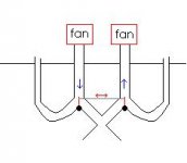
Why bother with helicopter gear (By means of 'pitch' of the blades) to change the amount of displaced air?
Why not instead use some vane/valve like device to conduct the required amount of produced 'air' into the listening room (And thus the 'rest' either somewhere else, or back into the device).
That will provide the 'forward' movement.
Do the same with another 'conduct' but this time 'suck' the air OUT.
Make both systems come together at one point, and in 'zero' position, both systems move the same amount of air, thus nulling eachother out..
When this "woofer's" cone moves down, the suck conduct will move more air out of the room, the blow part being still in zero, and the other way around.....
Would this work...?
(flame me!!! )
)
Paul
Just an idea
I had today...Why bother with helicopter gear (By means of 'pitch' of the blades) to change the amount of displaced air?
Why not instead use some vane/valve like device to conduct the required amount of produced 'air' into the listening room (And thus the 'rest' either somewhere else, or back into the device).
That will provide the 'forward' movement.
Do the same with another 'conduct' but this time 'suck' the air OUT.
Make both systems come together at one point, and in 'zero' position, both systems move the same amount of air, thus nulling eachother out..
When this "woofer's" cone moves down, the suck conduct will move more air out of the room, the blow part being still in zero, and the other way around.....
Would this work...?
(flame me!!!
)Paul
I have not looked up the construction, but I have noted there are some fan style devices which I believe are based on this principal.
Basically vanes in front of the fan (or behind or both) are opened or closed causing air to move in one direction or the other.
You would be limited to how fast you can move the vane(s). The bigger the slower... The bigger the fan the better the output as well
Basically vanes in front of the fan (or behind or both) are opened or closed causing air to move in one direction or the other.
You would be limited to how fast you can move the vane(s). The bigger the slower... The bigger the fan the better the output as well
This is what I thought..
Use some (radial) 'hot air heating'-fans.. 4000 m^3/Hr and there's plenty of air to move... 🙂 (like this )
Use one, or two strong servo-motors to move the vanes, damp the conducts to kill airflow noise.
Maybe one should put the vanes in opposit direction (inverse axle and lever) because in my 'drawing' the airflow will try to prevent them from coming back to 'zero'.
If it's too tricky to build with the vanes, maybe one could make a system where one fan 'sucks' half the volume/Hr of the other, and the other being modulated through a vane, by the signal. (like the first one drop the bias of the second one, Class A fan-sub!!!)
Cheers, Paul
Attachments
Unfortunately your design only takes air from one airspace and does not replace it from another.. you're only getting half the efficiency basically in other words.
This design is pretty simplistic for when there are two airspaces available.
EDIT - Looked closer and noticed one fan is moving air the opposite direction. Could work with some creative valving, but still inefficient.
This design is pretty simplistic for when there are two airspaces available.
EDIT - Looked closer and noticed one fan is moving air the opposite direction. Could work with some creative valving, but still inefficient.
Attachments
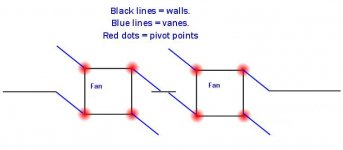
But it's (or it seems...) mecanically simpler ... One servo, actionning the two vanes...NVMDSTEvil said:Could work with some creative valving, but still inefficient.
Use HUGE fans (like the one I pictured) running at low speed to cope with the inefficiency (Less noisy as well!)
Paul
Maybe an alternative to the variable rotor idea would be to use a fan supplying a steady state pressure, but control the passage of air via an iris type assembly. If such a device could be made to act fast enough, there is your pressure modulation. Mabe a set of stators which could each be radially rotated through 90 degrees to either open the airway or close it completely. This would prove far simpler to construct, I'd have thought, the stators themselves consuming a nominal amount of power, with the maximum possible amplitude being determined by the power of the fan.
Such a system would presumably be better with two devices operating in push-pull, to enable rarification as well as pressurisation.
I should patent that.........
Such a system would presumably be better with two devices operating in push-pull, to enable rarification as well as pressurisation.
I should patent that.........
Either way it is done you will get the greatest effect by having the ability to move air in both directions.
If you only move it in one direction you will have very little net effect.
If you only move it in one direction you will have very little net effect.
Andy Westcott said:Maybe an alternative to the variable rotor idea would be to use a fan supplying a steady state pressure, but control the passage of air via an iris type assembly. If such a device could be made to act fast enough, there is your pressure modulation. Mabe a set of stators which could each be radially rotated through 90 degrees to either open the airway or close it completely... with the maximum possible amplitude being determined by the power of the fan.
Such a system would presumably be better with two devices operating in push-pull, to enable rarification as well as pressurisation.
I should patent that.........
I would imagine a linear vertical shutter would be more efficient, quieter and easier to arrange than an iris. Pneumatics would easily provide enough silent power over a long travel. Though I'm still wondering why a fan would produce a frequency range simply by having its flow partially restricted? The frequency response of the fan sub driver is a result of the variable pitch blades. Not the direct result of the fan itself rotating. Something has to be modulated to produce a usable frequency response.
How about putting a lightweight fan (muffin fan?) on a pivot. Place it at right angles to the output port so with no signal, as much pushes out as in. Then rotate it slightly clockwise or counterclockwise per the audio signal to modulate. Going one way will point some of the fan's 'out' toward the output port, the other way will point some of the fan's 'in' toward the output port... might work (?)

All you are really doing is directing or redirecting a constant airflow. The large shutters could not move rapidly enough to achieve a reasonable powerband frequency spread.
You still need something to rapidly modulate the airflow so that VLF soundwaves are produced. It's not enough to move the shutter at 1 Hz for a 1 Hz wavefront to be reproduced. There must also be an attack, sustain and decay.
The fan sub does this by superimposing pitch variations on the blades where they have maximum effect.
If you must stick with a constant speed fan you might have more luck with a lightweight slatted blind placed in front of the fan. The linked slats to be controlled by the audio signal. I imagine noise from air turbulence will be a serious problem unless the slats are optimised in form and thickness.
A centrifugal fan might be quieter than an axial one.
For an infrasonic subwoofer I think I'd prefer to experiment with huge polystyrene sheet ABRs driven by multiple, carefully distributed, small tuned ports of a series bandpass sub. The multiple ports would avoid plate flexure.
Nothing very original as such a design appeared in a magazine decades ago. This design had modestly-sized polystyrene sheet ABRs covering all four sides of the enclosure. I even got so far as building one of the ABRs myself using thin rubber sheet as the roll surround. I just didn't have a suitable LF driver at the time so gave up at that point.
presumtuous to think the large shutters cant move fast enough. I believe there is a sub out there which uses a 4' by 4' sheet of plywood and is able to obtain up to 15-20hz at 120db free-air isnt there? 10" stroke.
or 24" by 24". Details are a bit sketchy at the moment, but I believe it was built by Adire.
or 24" by 24". Details are a bit sketchy at the moment, but I believe it was built by Adire.
something like the adire parentheon..
or such,
There is a video of the motor assembly in action somewhere on google vid or youtube..
or such,
There is a video of the motor assembly in action somewhere on google vid or youtube..
Pantheon.
For some reason I had it in my head they called it the Apocolypse. Anyways i'm attempting to find the vid. I didnt know there was one out 😱
Found it
http://forum.carstereos.org/archive/does-pantheon-work-t57437.html
Video: http://www.realmofexcursion.com/videos/Adire/parthenon.1.wmv
edit - apparently the motor is called Pantheon. The sub they are buiding from it is the Apocalypse.
Who is getting busy with this?
That video makes it look like it can move something massive thru a long excursion, but only at about 2 Hz or so. Maybe it was slowed down (showing only a VLF action) so that it was visible in the video.
Regarding variable-speed fans: That's a lot of mass to slow down and speed up. That's one big reason why airplanes and helicopters don't do it that way. It is actually an advantage in having a constant speed fan to add more rotating mass. It tends to stabilize the speed of the rotation even though the load changes. The only place where extra mass hurts the efficiency of the design is in the blades, and then really only at the leading and trailing edges, not at the axis of rotation of the individual blades.
When the airflow is modulated the amplifier power only needs to twist the individual vanes (so there is some mass there and rotational inertia needs to be overcome. This component is actually the same whether the fan is spinning or not) AND overcome the pressure of the air (which is greater when the fan is spinning faster). This is very similar to the cmponents in a normal driver--you need to move the mass of the cone (which would be the same in a vacuum) and you need to move air.
One difference here is that with a conventional driver the cone mass is nearly always larger than the air mass being moved. (notable exceptions: massless exotics like ionic/plasma tweeters, and ultralight diaphragms like electrostatcs). With a fan spinning fast enough, the amplifier is driving more air than driver. Think about having your hand out the window of a car playing "airplane." Driving slowly, only a small amont of air is displaced, but when driving fast you can feel the displacement of lots of air.
One report on the ET site says the fan is spinning at a constant 12 revolutions per second or 720 rpm. I don't know the displacement of the blades, so don't know if the inertial mass neing moved is more air or more fan blade, but it is certainly possible to spin it fast enough to do this.
The ideal is to match the moving air mass with the moving driver mass. In this case, the collision becomes efficient. The attempt to match the air mass with the moving driver mass is pretty much the whole reason for horns and cabinents, etc.--the energy put into the cone should be transferred to the air, not stay in the mass of the cone or be reflected back to the amp.
A suggestion has been made a few time to add a DC bias to the rotation of the fan. In actual fact, it is just as easy to reverse direction as it is to speed up and slow down. Nothing is really gained there.
Suggestions were made that the fan operates much like a helicopter swash plate. That half true. The beauty of a swask plate is that it can be angled such that greater lift is generated on one side. In some cases, the life can even be positive on one side and negative on the other causing a helicopter to roll.
The swash plate is held steady, either flat or angled, and the blades sort of ride on it. When angled, they ride up on one side and down on the other.
The other control on a helicopter lifts the whole plate evenly, so all blades are given a grater pitch, and therefore greater lift.
What a helicopter does not ever do is more the swash plate up and down 20 times per second. ALL of the noise you hear from a helicopter or airplane is "noise" and wasted energy as far as a fan subwoofer is concerned.
LOTS of industral fans have a "variable pitch" available on their blades. These are changed electrically, pneumatically (air pressure), or hydraulically (liquid pressure). A standard available speed for flipping the blades is about 1 second to go one way. (2 seconds minimum for a complete cycle). These are designed to essentially blow one way in the morning and the other way at noon (or whatever) but are not really designed to "modulate" airflow (unless you want a 0.5 Hz tone as the highest frequency. They also use this capability to blow backwards to be self-cleaning. (Think about the fan of a car radiator - it is constantly sucking air, dirt and bugs theu the radiator. It it could flip the vanes every once ina while, it could blow the dirt back out.)
The way Thigpen is doing his rotary sub is pretty darned ideal. It would be helpful if we could measure its efficiency though. I remember reading that Danley's servodrive could produce 1 acoustic watt (I think it needed 1kW input to do this though). How much power could Thigpen's fan deliver intothe air from its 200-300 watt source?
If the fan didn't produce a lot of out of bandwidth noise (HF from air turbulence, and motor noise--we could just build it into a cabinet. As it is, his preferred design is to use it in a large (4th order?) enclosure where it doesn't fire directly into the roon, but first goes into a subroom and then is ducted into the listening area.
HIGHLY recommended that you read this, if you are really interested in knowing how the sub works and why it is so different than other subs:
http://www.iar-80.com/page142.html
You can find that link on the ET site as well. ("The ONLY Subwoofer")
One of the biggest points to get from that article is that the fan sub actually gains displacement as frequency drops. This is exactly what is needed to go low. A woofer moves more slowly at lower frequencies. The only way to maintain the speed it to move farther. This may be hard to visualize at first, but think of a woofer going 1 inch peak to peak at 40Hz and at 20Hz. It is travelling half as fast (and only transmitting 1/4 as much energy to the air).
With a fan woofer, the excursion goes up when the frequency goes down. It moves at a constant speed, so it just travels farther.
oops
Here's what I started to ask (and rambled on and totally forgot to ask):
Who is actually making one of these?
I would recommend starting from Thigpen's design and trying to get the price point down, as a good first effort. The ET subs are expensive because they are all hand built. Well, DIY gets free labor.
If you are looking at improving upon his design, I would recommend two areas:
[1] a thorough analysis of the shape of the individual blades. Remember that the outside tips of the blades are travelling much faster than the inside edges. The outside will experience much greater lift than the inside. This inequal pressure tends to flex the blades.
It also causes a big problem: whe the tips of the blade are pushing air HARD and the inner surfaces are not, it actually acts as if the center of the fan is sucking air when it should be pushing. This becomes a big point of inefficiency-the fan is fighting itself.
For a fixed blade (a non-variable pitch blade) this is handled by adding a twist to the blade, so that the angle of attack is greater closer to the center, and much lower at the tips. This was invented by the Wright brothers and has only been improved slightly in 100 years.
This will not work with variable pitch blades though. There, the standard handling is to make the blade much wider toward the center and narrower toward the tips. In this way the force is equal all across the blade, even though the tip may be moving 5 times as fast (linearly).
If the fan is noisy, this may fix a big component of that noise.
[2] the mechanism for moving the blades could likely stand some improvement. Make it simpler, or faster, or quieter, or cheaper to build. Thigpen's design uses a voice coil to to engage the rotation of the blades. This may be the most efficient way, but it must be darned complex if it makes an AC fan cost $13,000USD.
One idea is to look at using the other side of the fan for this control. The current design spins the fan and rotates the individual blades from the same side, so the two controls need to be concentric, with a center shaft inside of the voice coil assembly. If the angle of attack was controlled from the other side (the listening room side, I guess) this could be done with a rod pushing into the center (like 1/2 of a servodrive or something). A stepper motor could be used instead of a voice coil (would likely be less efficient, but more accurate control).
Remember that this fan really is an amplifier. It takes a whole bunch of AC power to drive a 1/3 horsepower fan. This power is then modulated by moving the blades, using only a few watts.
So who is up for really making some of these?
Forward swept blades will help for equalizing pressure across the entire blade.
Edit - Thigpen's use of a voicecoil to move the blades is not actually hard to do, the problem is transferring power to it while it is rotating really.
Given the frequencies being worked with, taking a walk back to the old days of electromagnets may be worth looking into to create a quasi-voicecoil assembly that works much as a maglev train or electromagnetic fan/water pump work, or similar anyways.
Re: oops
How to make a variable pitch fan, with variable angle of attack depending on diameter to improve efficiency.
Make the fan with a rigid ring around the outside edge.
the ends of the blades are fixed flat to the ring. so zero angle of attack at the rim.
the fan blades are twisted from the actuator near the centre just as normal.
the ends of the blades remain with zero angle of attack, increasing as you get closer to the centre. the blades twist.
Making the fan blades from composites will allow you to vary the thickness and therefore the flexyness and rate of angle of attack reduction as you progress from the centre out to the rim.
the fan is in a ducted fan arrangment with a bulb in the centre to accomodate the ring. so if you look through the duct you do not see the ring.
You read it here first. I've never seen anything like this before. Once you work the bugs out I'll sue you all for royalties. har har har.
I expect the rim will reduce the whooshing noise , the duct would be lined with material to absorb higher frequencies, the fan and actuator assemgly should be fitted with fairings front and back. Possible mounting the motor outside the duct on the garage side with a long shaft going inside the duct.
Here's a thought: Provide a DC offset channel to simulate wind (driving in a convertible?)
neededandwanted said:For a fixed blade (a non-variable pitch blade) this is handled by adding a twist to the blade, so that the angle of attack is greater closer to the center, and much lower at the tips. This was invented by the Wright brothers and has only been improved slightly in 100 years.
How to make a variable pitch fan, with variable angle of attack depending on diameter to improve efficiency.
Make the fan with a rigid ring around the outside edge.
the ends of the blades are fixed flat to the ring. so zero angle of attack at the rim.
the fan blades are twisted from the actuator near the centre just as normal.
the ends of the blades remain with zero angle of attack, increasing as you get closer to the centre. the blades twist.
Making the fan blades from composites will allow you to vary the thickness and therefore the flexyness and rate of angle of attack reduction as you progress from the centre out to the rim.
the fan is in a ducted fan arrangment with a bulb in the centre to accomodate the ring. so if you look through the duct you do not see the ring.
You read it here first. I've never seen anything like this before. Once you work the bugs out I'll sue you all for royalties. har har har.
I expect the rim will reduce the whooshing noise , the duct would be lined with material to absorb higher frequencies, the fan and actuator assemgly should be fitted with fairings front and back. Possible mounting the motor outside the duct on the garage side with a long shaft going inside the duct.
Here's a thought: Provide a DC offset channel to simulate wind (driving in a convertible?)
- Status
- Not open for further replies.
- Home
- Loudspeakers
- Subwoofers
- Fan Subwoofer