It's called "motor-boating", and is the result of the phase shift of the
transformer response at low frequencies. The cure is less positive feedback.
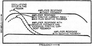
A nice reviewer for Stereophile sent me a copy of the 1957 article about
PCF, where they discuss this issue. They experienced a bump in the response
and potential instability (motor-boating) as they increased the pcf figure.
I don't recall them mentioning the cause, but it being 1957 it's a safe bet
that it was from the output transformer of the amplifier.
As noted previously, the other thing that can cause this problem in an amplifier
where a transformer used to process negative feedback is a high impedance
DC source - the amplifier wants to be DC coupled to some impedance.
In the F6 the input Fet buffer takes care of that.
Here is a curve from the article:
transformer response at low frequencies. The cure is less positive feedback.
A nice reviewer for Stereophile sent me a copy of the 1957 article about
PCF, where they discuss this issue. They experienced a bump in the response
and potential instability (motor-boating) as they increased the pcf figure.
I don't recall them mentioning the cause, but it being 1957 it's a safe bet
that it was from the output transformer of the amplifier.
As noted previously, the other thing that can cause this problem in an amplifier
where a transformer used to process negative feedback is a high impedance
DC source - the amplifier wants to be DC coupled to some impedance.
In the F6 the input Fet buffer takes care of that.
Here is a curve from the article:
Attachments
I knew it had something to do with water and thanks for the clarification and explanation. Presumably this would not happen in a F7 as the input is dc coupled. Could capacitor coupling between stages cause the same effect as would be inside the positive feedback loop.
Tom
Tom
I did the tweak today , Rsens 1.0 ohm , pot 50 ohms , 2 x 1.2 k ohms , 750 pf as filter caps , and i did move the negative of c1 and c2 .

the amp is still waming , and the "change" are not that huge , it seems more details added , and a little " plus" that i cant really explain , medium "look" more here , present , hard to tell in English .
Pot full left seems to be the place to be with those speakers , Triangle Zerius 202 , 4 ohms .
i made some mesurements to be sure that really something happens , here are the graphs .
it seems ( by mesurement) that the overall distortion is a bit lower than before the mod

blue is pot full left , green full right , and red at the middle .
unfortunately i could not put back my Wima MKP 10 , because i had no place for !!!
i will " ear" in the next day's , what is what , but nothing wrong anyway , the tweak is fully noise less , and quite easy to do , even for me 😀
.
Last edited:
In my case 1/2 hour is plenty enought for being "stable" .
it became an different amp with that tweak , I lost all my landmarks !!!
but seems to be very detailed , instruments are very well placed on the sound stage , voices are also clearer , more realistic , I found many smalls details that I havent heard before .
bass are tight enought , not louder anyway and not boomy at all .
what is sure is , the records have to be perfectly mastered , because it gives you out all , the good and the "bad"
F6 was and is an great amp , with that mod it become something new 😉
.
Last edited:
I replace the 1 ohm Rsens with an 1.5 ohm , just to ear what's happen.
it's better , seems a bit more dynamic , the overall behavior remain the same .
and I take out the pot , no need after all , and these kind stuff in the path of the PCF it's not really "audiophile" .
it's definitely an new amp , and hard to beat , I guess 😉
thanks to you all for having and share such cool very idea 🙂
.
Last edited:
Not sure I understand, did you move to 1.5 ohm and take out the 100 ohm pot and use feedback at that point. I found my 4 ohm speakers unstable as noted before at more than a 1/4 turn which would suggest your Rsen should be .375 ohms. Again I am not sure a direct feedback from the top of a .375 ohm Rsen is the same as the voltage divider feedback of 1.5 ohm with 1/4 turn of the 100 ohm variable resister. Perhaps someone more knowledgeable than me could comment.
Tom
Tom
Yes , I took off the pot , and replace the Rsens ( from 1 to 1.5 ohms ) , the signal goes directly to the fet through 2 x 1.2 k ohms resistors in series , simple as that .
the speakers datasheet tells 4 ohms , I measuring it with my Fluke 287 , 3.5 ohms not that far .
I am not able to tell you why it works so good , but it really sound great .
having heard about great and known hifi system , i am able to compare the sound "qualitity" they produce 🙂
.
the speakers datasheet tells 4 ohms , I measuring it with my Fluke 287 , 3.5 ohms not that far .
I am not able to tell you why it works so good , but it really sound great .
having heard about great and known hifi system , i am able to compare the sound "qualitity" they produce 🙂
.
Last edited:
Residual Distortion
Hi guys,
It would be interesting to present the residual distortion from the point that you felt to give the best sound. Maybe that will be similar to SET residual distortion.
Hi guys,
It would be interesting to present the residual distortion from the point that you felt to give the best sound. Maybe that will be similar to SET residual distortion.
the THD measured by SPL is lower , not much and not along the all graph , but lower .
and its dominant 2th harmonic till 2 khz , my F6 have R1 and R2 0.47 ohms .
.
and its dominant 2th harmonic till 2 khz , my F6 have R1 and R2 0.47 ohms .
.
the THD measured by SPL is lower , not much and not along the all graph , but lower .
and its dominant 2th harmonic till 2 khz , my F6 have R1 and R2 0.47 ohms .
.
If you sim your amp with R1 and R2 equal you get dominant 3rd harmonic (about 15db difference).The dominant 2nd harmonic is with the top R (on the schematic) larger (0.56 ohms) and the lower R with 0.47 ohms again about 15 db difference.I think you must be measuring something else?Also if you lower your positive feedback resistor to 2.2K ohms total you will get better damping factor.
Last edited:
I dont have to simulate anything , in my real world it happens as I said , R1 equal R2 second harmonic dominant , the reasons are unknwon to me , but that's it , and I am happy with that result 😉

the cursor was place at 1 khz
the two feedback resistors ( vishay metal film ) in series made 2.309 kohms , the Rsens (non inductive ) is 1.50 ohms / 10 w .
.

the cursor was place at 1 khz
the two feedback resistors ( vishay metal film ) in series made 2.309 kohms , the Rsens (non inductive ) is 1.50 ohms / 10 w .
.
Last edited:
I dont have to simulate anything , in my real world it happens as I said , R1 equal R2 second harmonic dominant , the reasons are unknwon to me , but that's it , and I am happy with that result 😉
the cursor was place at 1 khz
the two feedback resistors ( vishay metal film ) in series made 2.309 kohms , the Rsens (non inductive ) is 1.50 ohms / 10 w .
.
Looks very good.. Appreciate it if you can share the schematics for your mod? There's a few variant floating around and it is normally clearer for me if I see it visually.
What speakers are you using?
Thanks!
You'll find the schematic at post 49 , you can add an pot to the Rsens if you like , 50 or 100 ohm , to find the perfect fit .
i talk about my speakers in previous post 🙂
.
i talk about my speakers in previous post 🙂
.
I made some measurement today , i want to understand what is the amount of current that goes back to the jfet , so the imput .
i sent a 1 khz / 517 mv signal to the amp , that gives me :
1.97 v at the speakers ( Z : 3.5 ohms)
91.1 dBc / -33.5 dBfs at 1 m
171 mv across the 2.3 kohms resistor
453 mv across the Rsens /1.5 ohm
am i wrong saying that the PCF is 74 uA ??
.
i sent a 1 khz / 517 mv signal to the amp , that gives me :
1.97 v at the speakers ( Z : 3.5 ohms)
91.1 dBc / -33.5 dBfs at 1 m
171 mv across the 2.3 kohms resistor
453 mv across the Rsens /1.5 ohm
am i wrong saying that the PCF is 74 uA ??
.
Same measurement but Rsens 1.0 ohm
i sent a 1 khz / 501 mv signal to the amp , that gives me :
1.81 v at the speakers ( Z : 3.5 ohms)
90 dBc
194 mv across the 2.3 kohms resistor
277 mv across the Rsens /1.0 ohm
am i wrong saying that now the PCF is 84 uA ?
if so , the PCF is greater with an lower Rsens ?
at the end , sound is more "confortable" using the 1.0 ohm Rsens , it's detailed as before but smoother to my ears , i have to admit that its quite hard to find the "good" with all these changes , and psycho-acoustic doesn't help !!
.
Last edited:
if so , the PCF is greater with an lower Rsens ?
.
i´m the wrong guy to answer, cause i´m a "noelectrix", but i guess PCF increases with increasing sense-R? With the suggested pot on zero
Ohms, no VOltage or current should go to input.
I ordered 50 ohm pots like ZM and circlomanen suggested. what a lark, what a plunge : )
Right. If the sense resistor is 0 ohms, there is no PCF.
For those with a mathematical bent (algebra) check out Lhquam's excellent
and comprehensive posts on the formulas for various configurations.
For those with a mathematical bent (algebra) check out Lhquam's excellent
and comprehensive posts on the formulas for various configurations.
Fact is , I dont know how PCF really works , so even if I measure some stuff around , that doesn't help me so much 🙄
it make sens anyway that PCF increase with Rsens , I may try to measure it an other way😉
the sound tale anyway , and it's pretty "clear" 😀
.
it make sens anyway that PCF increase with Rsens , I may try to measure it an other way😉
the sound tale anyway , and it's pretty "clear" 😀
.
- Status
- Not open for further replies.
- Home
- Amplifiers
- Pass Labs
- F6 with PCF