Johannes "Circlomanen" suggested I start this new thread. PCF fascinates me and the F6 may be a place to start since I already have the amp.
Here are suggestions he made.
Originally Posted by wdecho View Post
I would love to see some electronic guru's design a schematic for the F6 using some positive feedback for us solder slingers to experiment with. Now that I have my M2 built I would love to play with the F6 circuit that uses negative feedback and introduce some positive. Nelson says it can be done with other amplifiers as well.
It is quite easy.
Just add a 0,5 ohm (or less value) power resistor between the speaker and ground. Use a small 100 ohm 2 watt potentiometer parallel over the 0,5 ohm resistor and couple the middle tap to the input of the Jensen transformer. With a transformer in the positive feedback loop I would be very careful and very very slowly increase the positive feedback. Remember to use fast fuses and have several matched pairs of spare output transistors at hand....
If trying this method I would like to have some kind of sacrificial loudspeaker connected to the amp, since it can get truly wild very fast...
Cheers,
Johannes.
Him and I hope Mr Pass will help and keep us from smoking.
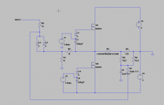
I am very tired today, so please excuse any errors I might have made.
This is the way I would PCF-itize the F6.
R5 and R6 is the 100 ohm potentiometer I wrote about.
C3 is some lowpass filtering to reduce the tendency for oscillation. 10 nF is just a guess.
I have not built this amp, so this is all very experimental and theoretical.
Please try this at your own risk, and please don't blame me when your output transistors and/or speaker has vanished in a violent shrieking bang.
The transformer within a positive feedback-loop makes me very uneasy, even though I am certain that some PCF can and should be used for certain speakers and loads. Transformers are a good basis for oscillators, and backed by the power of two high power mosfets they will jump with ferocious appetite at any reason to oscillate.
I don't want to dissuade anyone from trying this. I just want to stress some caution. Check and double-check that the potentiometer is turned all the way down before turning on the amp. Use some kind of resistors (lightbulbs) in series with the amp and use a fast blow fuse.
If the amp starts sounding metallic, hollow or distorted then you are way to close to the edge. Back down on the amount of PCF fast.
I think this is a very interesting subject. I would really like to build a F6.
Cheers,
Johannes
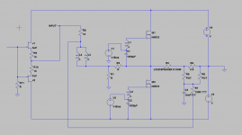
This is the Jfet-buffered version.
The input buffer is also a place where you can tap some PCF into.
It might make the amp more stable and easier to drive, since you don't demand to much from the transformer. I am not sure though. As I said. I have not built this. I can't make any guarantees. This is just suggestions on how to get started in exploring the PCF boosted F6. I am currently exploring the PCF-Zen(ish) amp, and there is so many ways to tune and adjust everything that is is truly mind-boggling.
The F6 increases this by an order of magnitude.
It is like looking out over the pacific ocean for the first time. It is a vast and expansive subject. I am at awe over the pure genius behind this seemingly simple amp.
It is truly a work of art.
Cheers,
Johannes
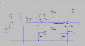
Here I have rearranged the positive current feedback and the input buffer to something working similar to my experiments with the Zen amp and PCF.
This is just an idea. Please check for any errors. I believe it should work with the right balance between NFB and PCF, otherwise I would not have posted it. I have not built it so I don't want to claim this to be the end all definitive version of F6-PCF.
Cheers,
Johannes
Thanks Johannes. I am not afraid of sparks and smoke and every builder should have some sacrificial speakers. Even they are easy to fuse. Caps popping are an eye opener though. If none of these things have happened to you, you are not experimenting enough.
I think most have built the F6 with the jfet version. I will assume where it says input is just the signal coming from the jfets and nothing is hooked there.
It would sure be nice to get Nelson's input of this. Maybe we have sparked his curiosity enough to comment.
It would sure be nice to get Nelson's input of this. Maybe we have sparked his curiosity enough to comment.
Another question, R3 is this the speaker? If so I see the feedback circuit as being taken from the - of the speaker out. I am sorry for my inexperience reading schematics.
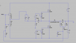
This would probably be the preferred way to couple the PCF into the input-buffer.
You sense the amount of current through the speaker with a small value resistor between the - speaker and ground. This small signal should then be coupled back positive into the amp. Whenever the positive feedback senses a large current through the speaker, it will increase its power output, instead of decreasing it. This can then overcome the normally poor damping factor of the amp by supercharging it at need.
It is like looking out over the pacific ocean...
Probably that's what I was doing when I thought of it.
😎
Johannes I do have one question about the 100 potentiometer. In the schematic you show R5 and R6 as pot. From your description this is just one pot. Am I correct? Also what are the values of the R11 and R8 resistors? The circuit does not look hard to implement in the F6. I have 2 complete FW clones and with my speakers I like my new M2 better. With horns the M2 really shines so I do not mind playing with the F6 some. My amplifier is built form this schematic.
http://www.diyaudio.com/forums/gallery/data/500/F6_DIY_SCH.gif
with R5 being a 1k and R6 47k. Am I to remove the R5 and R6 and replace them with R11 and R8 as shown in your schematic. I would think you still would need the R5 1K input resistor but I could be mistaken. What values of R5 and R6 would you use?
Last edited:
From your description this is just one pot. Am I correct?
Yes. One single linear 100 ohm (or 200 ohm) pot. It should probably be at least a 1 watt type. I would use a Bourns Cermet 2 watt (652-3852A-282101AL Mouser art nr).
What values of R5 and R6 would you use?
I don't know. I have never played with this kind of amp. Your guess is probably as good as mine.
I can't even make up my mind if it is better to couple the positive feedback to the gates of the input jfets or the junction between the sources of the input jfets (Q3 and Q4 in the schematic you linked to in your previous post) and the transformer.
After some thinking about this problem I would start out with coupling the positive feedback directly to the transformer input as in my picture below.
If you couple the positive feedback to the gates of the jfets, you can get all sorts of strange phenomena with the cables and eventual coupling capacitors in the preamp.
I guess it is better to focus all the feedback to the transformer and keep it within the amp. It is bad enough that you are sensing what is happening in the speakers.
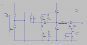 '
'R7 and R9 in my schematic is just a suggestion to get you started. It is there to give some low pass filtering of the positive feedback and to somewhat dampen the positive feedback so it is easier to control. These values are just a guesstimate. C3 can probably be a 100 nF capacitor. You don't want any positive feedback above the audio band (to avoid RF-oscillation).
Cheers,
Johannes
I have one PCF board built and I am thinking of putting the signal at the output of the transformer instead of the input. The transformer is not like the M2 with voltage gain but is there to invert the signal where 2 common transistors can be used in a push pull fashion. Actually on the F6 schematic pins 3 and 4 are the output pins and 1 and 2 the input. Unless I am mistaken the negative feedback in injected back into the circuit through R8 and R4 so injecting the PCF at the junction of R18 and the output of the transformer may be better. Any opinions, recommendations are cheerfully welcome.
Unless I am mistaken the negative feedback in injected back into the circuit through R8 and R4 so injecting the PCF at the junction of R18 and the output of the transformer may be better.
R3 and R4 determine the negative feedback. R8 sets the current through the zener Z2. I don't see any R18 at all.
My fault, R8 the 10K is what I meant. I was looking at the 18 ohm R4 and calling the one under it R18. I put the input from the PCF at the junction of R3 and R4 with no difference in the sound. I then put the input of the PCF at the junction of 1 & 2 of the transformer, no difference.
I will double check my board and make sure everything is correct tomorrow. I installed the PCF at the negative of the speaker. If R3 is the speaker the PCF circuit should go to the negative of the speaker. Maybe I am wrong. I see the other end of R3 as going to ground. It is obvious I need some help.
I will double check my board and make sure everything is correct tomorrow. I installed the PCF at the negative of the speaker. If R3 is the speaker the PCF circuit should go to the negative of the speaker. Maybe I am wrong. I see the other end of R3 as going to ground. It is obvious I need some help.
Last edited:
SPICE simulations are suggesting that modest amounts of PCF lower overall THD in the F6 (by cancelling some second harmonic). But this is the opposite of what I expected based on NP's comments (a little PCF in F5 yielded lower output impedance at the cost of slightly higher overall distortion). At any rate, the changes in THD I've noticed have not been large, so I don't know that you'd notice a huge difference in sound.
I am use to building from a conventional schematic but some of the signs from the computer generated schematics are somewhat confusing to me. If R3 is the speaker I see it as both terminals of R4 are going to ground which I do not think is correct.
With the PCF as in the schematic above, the negative speaker terminal is left floating, not grounded.
Edit: I just realized you may be using part number references based upon Circlomanen's schematic and not the stock F6 schematic. So, you can disregard what I said above about R3 and R4 determining negative feedback (which is true of the stock F6 schematic). In his schematic, R1 and R2 set the negative feedback.
Edit: I just realized you may be using part number references based upon Circlomanen's schematic and not the stock F6 schematic. So, you can disregard what I said above about R3 and R4 determining negative feedback (which is true of the stock F6 schematic). In his schematic, R1 and R2 set the negative feedback.
Last edited:
- Status
- Not open for further replies.
- Home
- Amplifiers
- Pass Labs
- F6 with PCF