Thank you for your help, DennisYup. That's also what I see.
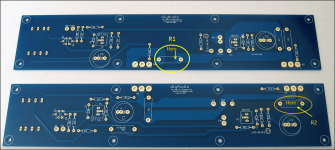
I have added a diagram to clarify and to assist others. Wayne
Attachments
Last edited:

Just wrecked my F6 when measuring bias. Had set my multimeter to ampere instead of Mv and something started to smoke. Will need to take the board out to properly inspect, but does anyone know which part(s) I may have damaged?
the MOSFETs would be the 1st guess. Best to pop the top and take a peak.
Are you able to hook it up to an o-scope to look at the output?
Are you able to hook it up to an o-scope to look at the output?
Have visually inspected the resistors and all seem fine. Remember looking at both DMMs and, without changing the trim pots, the offset was completely off (way too high). Bizarre as the amp was working fine before remeasuring the bias and offset. Before I measured bias in Mv instead of ampere. Teaches me to stop fiddling when things are working.
Attachments

Hi Dennis, As there was smoke coming out of one of the components, I've not dared to fire it up again. Resistance R1 and R2 in circuit on board A are 0.7ohm.What voltages do you measure across R1 and R2?
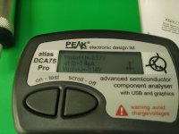
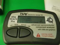
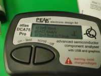
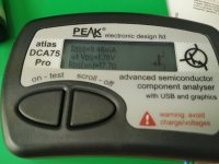
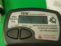
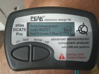
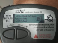
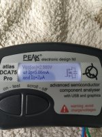
I also pulled one of the irfp 150 MOSFETs and it measures as follows:
Attachments

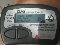
If you were attempting to measure the bias across one of the source resistors with your DMM set to measure current, what you've effectively done is put another low-resistance path in place of the source resistor. Your DMM manual should tell you the value, but it's not too relevant. Given that the source resistors are 0R47 and 0R56 ... although you saw / smelt smoke, you may not have hurt much given that you likely did not change the current through the associated part 'dramatically'. I'd first check the output MOSFET directly associated with the resistor you were measuring across. It may measure OK on something like your Peak. However, I'd inspect the back of the part for visual thermal damage. If you have another pair of output devices, it couldn't hurt to swap them, particularly since you've already got the board out and one part removed.
My $0.02, and I'm sure I've likely missed something, or that I could be dead wrong. However, that's where I'd start the path to verification and a bit of the logic behind it.
Good luck!!!
BTW - if you have a DBT and/or a Variac, now may be the perfect time to back the bias back off and slowly ramp back up while taking a few measurements to check operation. You may have gotten pretty lucky and just heated up a part a bit too much w/o killing it. They're fairly robust. Also, if your amp is properly fused, you'd likely have blown a fuse before too much could go haywire unless you were quick, quick, quick to turn it off.
If you were attempting to measure the bias across one of the source resistors with your DMM set to measure current, what you've effectively done is put another low-resistance path in place of the source resistor. Your DMM manual should tell you the value, but it's not too relevant. Given that the source resistors are 0R47 and 0R56 ... although you saw / smelt smoke, you may not have hurt much given that you likely did not change the current through the associated part 'dramatically'. I'd first check the output MOSFET directly associated with the resistor you were measuring across. It may measure OK on something like your Peak. However, I'd inspect the back of the part for visual thermal damage. If you have another pair of output devices, it couldn't hurt to swap them, particularly since you've already got the board out and one part removed.
My $0.02, and I'm sure I've likely missed something, or that I could be dead wrong. However, that's where I'd start the path to verification and a bit of the logic behind it.
Good luck!!!
BTW - if you have a DBT and/or a Variac, now may be the perfect time to back the bias back off and slowly ramp back up while taking a few measurements to check operation. You may have gotten pretty lucky and just heated up a part a bit too much w/o killing it. They're fairly robust. Also, if your amp is properly fused, you'd likely have blown a fuse before too much could go haywire unless you were quick, quick, quick to turn it off.
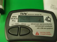
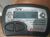
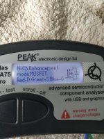
I've measured the second IRFP150 and it measures practically the same as the other (see photos).
Should I just order 2 new ones or just use them? Also, should I replace the MOSFETs on the other board as well (they might match better if from the same batch)
Attachments


And you would hook the amp up to a scope? Do you mean at the speaker terminals? What should I look for?As @ItsAllInMyHead relayed (heh), if you can control the power up, give them a go and see.
First power them up and see if you can set bias and offset.
If not, then, yes, something is toast.
2nd, if they bias up fine, hook the o-scope up to the binding posts for the possibly offensive channel. Feed the channel a 1kHz sine wave and see how it looks on the scope.
If 2nd worked, then try it hooked up to a load to see how the current delivery is holding up. A non-reactive 8ohm dummy load would be better but can use your speaker.
Have ordered new MOSFETs and will follow your instructions once installed. Thanks for your help.
- Home
- Amplifiers
- Pass Labs
- F6 Illustrated Build Guide