You have no option left really but to test each of the JFETs out of circuit to check their Idss and if they work according to spec.
You might check to make sure your source signal hasn't any dc offset before you pull the amp apart - just saying ...
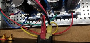
I put shrink tubing around my input transistors for temp tracking. Then I started second guessing. Will that cause too much heat buildup?
Just check with you DMM if there's any dc voltage on the output of your source (ie the out[put phono socket on your preamp, etc) - it's such an obvious thing and I've been caught out with this myself.
I didn't have this amp up and running. Still trying to get the B channel to work.
So it wasn't connected to any source.
So it wasn't connected to any source.
Ah, well that rules out that idea - it looks like you're going to have to pull those jfets and test them after all as there's not much else left to try as the posts above have indicated.
I have notice many firstwatt amps have boards and devices mounded horizontally on maybe an L bracket? Bolted to the heatsink. If I have large enough aluminum L channel, as long as I keep the mosfets on the inside close to the heatsink is there any reason not to do this? I would bolt the bracket to the heatsink using silver heat goop.
You would add a thermal junction and lower the heat-transfer (the heat-sink capacity) by the rate of the thermal resistance of that junction. So, the lower this resistance you can achieve, the less impact you get.
You have to make sure the connection is as precise as can be to guarantee the smallest loss.
(And, since it is a heatsink-heatsink connection, you could use „electrical conducting“ stuff like panasonics carbon thingies)
Here‘s a very good resource (long read): Taming the LM3886 Chip Amplifier: Thermal Design – Neurochrome
Been using my F6 for a week now. The amp has CL-60s in the transformer primary, Antek 400VA.
Is a soft start circuit worth it?[/url]
I have relay/bypass for cl60 which works well
Per the input I received I:
Changed R6 to 47K
Checked all parts
No solder issues with JFets
Checked Mosfets for continuity
Turned on with dim bulb, it faded, but R4 smoked
My readings today:
Bias 0.00 mV
Offset 223.0 mV
R1 46.5 mV
Researching this forum I turned up PJN who reported a smoked R4 in one channel after using the amp for five months. He ended up replacing the JFets as the consensus was they were blown due to high offset voltage. [#500 thru #521].
ZenMod concluded high output offset and suggested to check the JFets out of circuit. It could be that when I first turned on the amp the output trimmer was set way too high and that is when I toasted the JFets? Working hypothesis given the 223.0 mV output reading today the pot is still set way too high?
I can test the JFets and replace as needed.
Is there anything else I should consider?
Thanks for the help as always.
Saturday Update:
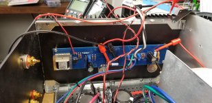
I removed the JFets and found one not working properly. See attachment.
I replaced the R4 resistor [again.]
I will put a new set of Jfets in.
And make sure my trimmer pots are set around 1.50 ohms. Is that low enough? Once burned, or twice burned makes me cautious.
Attachments
Thanks for pointing that out
Zen Mod,
Is BJT-NPN incorrect for identifying a LSK170 Jfet?
I went back and tested the two JFets with two testers.
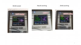
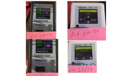
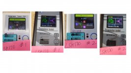
The Longrunner tester identifies the LSK as a NJFet. The transistor tester identifies it as as BJT-NPN. Is this tester wrong? I'm confused, as BJT-NPN shows up in searches for the LSK170. I also noticed that the D - G - S are shown reversed in the two testers? Is the transistor tester not accurate?
The same pattern shows for two new LSK170s I tested.
They both miss identify the old LSJ74 as a resistor which suggests that it is bad.
Thanks
Zen Mod,
Is BJT-NPN incorrect for identifying a LSK170 Jfet?
I went back and tested the two JFets with two testers.
The Longrunner tester identifies the LSK as a NJFet. The transistor tester identifies it as as BJT-NPN. Is this tester wrong? I'm confused, as BJT-NPN shows up in searches for the LSK170. I also noticed that the D - G - S are shown reversed in the two testers? Is the transistor tester not accurate?
The same pattern shows for two new LSK170s I tested.
They both miss identify the old LSJ74 as a resistor which suggests that it is bad.
Thanks
Attachments
LSK and LSJ are NJFet and PJFet, respectively
if meter sez different, either part is bad or meter is bad
if other meter sez properly, end of puzzling - always use that meter for checks, ignore other one
if meter sez different, either part is bad or meter is bad
if other meter sez properly, end of puzzling - always use that meter for checks, ignore other one
I recently tested a batch of LSK and LSJ on one of the generic mega328 testers. All were identified correctly except one LSK170 which was wrongly identified as an npn bjt. I assume it (the jfet) is faulty.
ok. To recap:
I turned on the right channel with a 100 watt dim bulb in place.
The bulb dimmed.
And then R4 smoked.
I fried Q4.
I also had a 47R instead of a 47K resistor in R6.
I think this happened because I had P1 set way too high.
I have now replaced all three pieces and set P1 to 1.145k ohms
and P2 to 1.86 k ohms, so I should not overload Q4.
Before I start up, is there anything else I should consider?
Thanks,
Attachments
How did you come with the P1 and P2 values you mentioned? What do you mean by “setting P1 too high”?
Best,
Anand.
Best,
Anand.
- Home
- Amplifiers
- Pass Labs
- F6 Illustrated Build Guide