1. just take DC from one rail and GND, put appropriate resistor in series; if you need help to calc it, just write here what's current thingie is consuming at 6Vdc
2.depends; first say which one exactly you have on mind
3. not exactly helpful there, being on other side of pond, so not exactly familiar with tool you're having at near store; stepped drill is most friendly, but you need to drill from both sides to get overall depth and even then you'll most probably get step in a middle; whatever you use, preferably stand drill ( not hand-drill) , apply some liquid - at least WD40
Thank you Zen Mod. Power switch LED (red) measures 0.01ma at 6vdc. Would appreciate your resistor calculation.
Protection board is a generic pre-built w/3s delay and requires 12vdc source and draws 0.01-0.02ma per DMM. Although for some reason my DC power supply show 0.05a. Still researching whether to use this board or not.
Will use table top drill press on front panel (w/lube per your suggestion).
Thanks again for your help.
well, check your measuring routine ........ or your typing 🙂
please, mA, A, be precise - both in measuring and typing here
(ma is pretty much understandable typo, but invoking doubt)
please, mA, A, be precise - both in measuring and typing here
(ma is pretty much understandable typo, but invoking doubt)
yes. trimpots set to 0 Ohms, as I explained
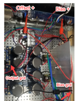
then, if everything is assembled properly, with two voltmeters connected per 6L6 first post, start amplifier via Variac from 0 to full mains voltage, observing Iq and DC Offset
then, simply proceed with setting procedure (mentioned post)
simple as that
work with one channel connected to PSU at a time, if you feel safer that way, insert temporary F2A5 fuses in both rails
I was able to set the pots to be used in A channel [I have not built the A circuit board yet.]
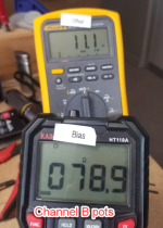
But the pots installed in B channel are stuck at 78.8 ohms for bias and 11.1 ohms for output. Stuck because for both I'm at an end where I hear the clicks.
See photo of where I placed the leads. This was the best result I could get testing the leads on the top or bottom of the resistors.
Are these pots shot? Something else going on? I'm ready to pull the pots and replace them, setting them at 0 ohms before I solder them in.
Attachments
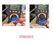
Measurements are mA. Thanks.
well, I don't believe you
you'll hardly find relay needing less than 20mA at 12V, speaking of speaker delay/protection board
show us how you're measuring that
maybe you're good, but battery in your DMM isn't
I was able to set the pots to be used in A channel [I have not built the A circuit board yet.]
But the pots installed in B channel are stuck at 78.8 ohms for bias and 11.1 ohms for output. Stuck because for both I'm at an end where I hear the clicks.
See photo of where I placed the leads. This was the best result I could get testing the leads on the top or bottom of the resistors.
Are these pots shot? Something else going on? I'm ready to pull the pots and replace them, setting them at 0 ohms before I solder them in.
11.1R is sorta OK, but 78R is suspicious
if I could trust that pots are having no shocks in previous history, I would say - just imperfect fabrication on end of range; but I can't count on that and my advice is to change them
Thanks. And I'm a wee bit better sorted out on Trimmer pots. So it's worth the learning process.
Is this just a bad pot, if so could it have caused the R4 resistor and Jfet to fail?
Or I had the pot wide open and that took it out and the stuff above?
Is this just a bad pot, if so could it have caused the R4 resistor and Jfet to fail?
Or I had the pot wide open and that took it out and the stuff above?

Thanks. And I'm a wee bit better sorted out on Trimmer pots. So it's worth the learning process.
Is this just a bad pot, if so could it have caused the R4 resistor and Jfet to fail?
Or I had the pot wide open and that took it out and the stuff above?
This just in:
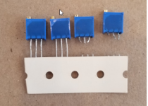
I removed the two pots. Upon closer examination the four pots I got in the parts kit from the store all say 3296 on the side, which Mouser shows is a 4.7K pot, not the 5K listed in the BOM. Also the two I used show: W502 021Co on the top. The other two show 804C0 W203 on the top.
It seems odd that I'd get two different markings on the four pots all on the same strip arranged together?
Should I use 5K pots or is 4.7K close enough?
Just when I thought I knew my pots.....
I hope it is not what I think you are doing. Did you put the DMM leads in the DMM in black (GND) and mA holes? And did you put the other end on the 12V input connector?Probably doing something wrong. Attached is a photo of the measurement.
If so, the fuse of your DMM is blown. Current measure must be done in series not parallel.
Your protection board is 12V / 50mA according the power supply display.
Last edited:
Probably doing something wrong. Attached is a photo of the measurement.

plenty of ootoob vids and other online tutorials how to measure current
DMM must be in series with source and load
Thanks. Please forgive my error. The protection board draws 50mA @ 12vdc. Can this amount of current (with voltage step down resistor) be drawn direct from the rectified dc output without negatively impacting sound quality?
Thanks again.
Thanks again.
You cannot do this with a resistor. Almost all current is for the relays. If they are not activated, then the voltage on the protector board would jump up to almost the power supply voltage of 24V. Best to use a regulator.
Chiptech, 3296 is just a trimmer model and does not refer to a particular resistance
value. If unsure, you should just measure their values (at the pins at the two ends)
value. If unsure, you should just measure their values (at the pins at the two ends)
Thanks. Please forgive my error. The protection board draws 50mA @ 12vdc. Can this amount of current (with voltage step down resistor) be drawn direct from the rectified dc output without negatively impacting sound quality?
Thanks again.
include simple reg. cell with 7812, to bring voltage from positive rail
though , depending of actual schematic of protection module , there can be more to that
post schematic or extragood picture of module, and we'll know
Chiptech, 3296 is just a trimmer model and does not refer to a particular resistance
value. If unsure, you should just measure their values (at the pins at the two ends)
Dennis,
Thanks. I measured the two I had been using:
W502 021C0 4.7 ohms
W502 021C0 4.925
The other two that came from the same strip in the F6 parts kit are different.
804C0 W 203 18.79 ohms
804C0 W 203 19.92 ohms
So lesson learned. I didn't think to test these pots since they came from the kit. My bad. I can't explain why the second two are 20K pots, but I won't be using them.
Good catch.
Attachments
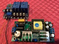
Could not locate a schematic for the generic speaker protection board (12vdc, 50-60mA). Attached is a close-up. The other board is a 120vac to 12vdc step down rated at 2A (2000mA). What do you think about this as an option? Any adverse impact to sound quality?
Thanks.
Thanks.
Attachments
Could not locate a schematic for the generic speaker protection board (12vdc, 50-60mA). Attached is a close-up. The other board is a 120vac to 12vdc step down rated at 2A (2000mA). What do you think about this as an option? Any adverse impact to sound quality?
Thanks.
is speaker board power clearly labeled as 12Vdc?
- Home
- Amplifiers
- Pass Labs
- F6 Illustrated Build Guide