This is true. I ordered a set of 10 FQH44N10 Mosfets, and just grabbed four of them for my F6. Sounds pretty amazing. I put more work into other parts of the amp. Now I'm following up on a recommendation by 2 picoDumbs to tweak the source resistors for Q1. Really wish the F6 PCBs had an option for this, but I work with what I have. 😀Acoustic emotion - for all practical purposes, that is a matched quad of Mosfets. Use wherever you like. 🙂
Also, F6 does not require tight matching in Mosfets.
It's a case where that tweaking isn't going to do much because of the 600lb gorilla in the room, the transformer.
If you want an amp where you can tweak that and it actually means something by changing the harmonic balance, try an F5, or my absolute favorite, BA-3. 😀
If you want an amp where you can tweak that and it actually means something by changing the harmonic balance, try an F5, or my absolute favorite, BA-3. 😀
Thank you for your reply.
Is there any reason why?
You got some excellent, detailed answers. My simple answer was based on the information in front of me along with some broad assumptions.
Sadly with me, you get a wall of text with reasoning... or a short answer. Most people like short answers. 😀 I told you where to put them. That's what you asked. It'll work. I never said it was the best way to put them in b/c I don't have definitive information to know if it is or isn't. Neither does anyone else. Now that you've stated you have a theory...
My amended answer is -
It likely won't matter, but...
If you'd like to test your theory on imaging. Go ahead. It can't hurt a thing, but you don't have a control to test that theory. So, I'd go with what makes you happy. Your brain and ears will likely thank you b/c making the "right" decision could affect how the amp sounds to you (if you believe in such things).
 and congrats. Can't wait to hear your impressions!!
You got some excellent, detailed answers. My simple answer was based on the information in front of me along with some broad assumptions.
Sadly with me, you get a wall of text with reasoning... or a short answer. Most people like short answers. 😀 I told you where to put them. That's what you asked. It'll work. I never said it was the best way to put them in b/c I don't have definitive information to know if it is or isn't. Neither does anyone else. Now that you've stated you have a theory...
My amended answer is -
It likely won't matter, but...
If you'd like to test your theory on imaging. Go ahead. It can't hurt a thing, but you don't have a control to test that theory. So, I'd go with what makes you happy. Your brain and ears will likely thank you b/c making the "right" decision could affect how the amp sounds to you (if you believe in such things).
I totally agree with you! Your answer was correct and very helpful.🙂
You’re right about putting them in b/c or not, it will probably not be audible anyway.
The reason I asked why (and maybe I should clarify, when I ask such a question) is because I am completely new to amplifiers and I just want to know as much as possible background information. I have no electrical background so I just try to pick up as much as people want to share. Thanks to this forum I learned a lot.
Maybe I am very sensitive to something called psycho acoustics, when I THINK some minor deviation will affect the sound, then I maybe THINK I will hear this when running the amp. So, to avoid this crazy phenomenon I will just make left and right channel as identical as possible. Just for the ease of mind.
Thank you for your time to clarify your answer, and I will share my impressions later (especially how identical the channels sound ofcourse 😉😉😉 )
TungstenAudio,
Maybe the Tea-Bag F6 Convertible Clone PCB can be your platform of choice for the F6?
With that PCB you can swap in/out 3 different types of transformers (Jensen, Cinemag, Onetics), and can also tweak source resistor degeneration with the help of trim pots. 🙂
Maybe the Tea-Bag F6 Convertible Clone PCB can be your platform of choice for the F6?
With that PCB you can swap in/out 3 different types of transformers (Jensen, Cinemag, Onetics), and can also tweak source resistor degeneration with the help of trim pots. 🙂
Last edited:
Or this, and build any version imaginable.
https://www.diyaudio.com/forums/group-buys/310775-gb.html#post5149348
https://www.diyaudio.com/forums/group-buys/310775-gb.html#post5149348
^ This is an interesting question. I might suggest that the matched pairs be used in the same location in each channel. This could improve the matching of performance between the two channels, and therefore imaging.
Absolutely , it isn't a theory , it's a fact , but obviously one should have the good set up to notice it , source , speakers , etc..
some/many haven't so they cant hear any difference 😀
.
Last edited:
You got some excellent, detailed answers. My simple answer was based on the information in front of me along with some broad assumptions.
Sadly with me, you get a wall of text with reasoning... or a short answer. Most people like short answers. 😀 I told you where to put them. That's what you asked. It'll work. I never said it was the best way to put them in b/c I don't have definitive information to know if it is or isn't. Neither does anyone else. Now that you've stated you have a theory...
My amended answer is -
It likely won't matter, but...
If you'd like to test your theory on imaging. Go ahead. It can't hurt a thing, but you don't have a control to test that theory. So, I'd go with what makes you happy. Your brain and ears will likely thank you b/c making the "right" decision could affect how the amp sounds to you (if you believe in such things).
which things ?? , can't wait to read about 😀
.
Well, I didn't realize that some of the earlier F6 boards were still in play. I've managed reasonably well so far with the store F6 boards and Jensen signal transformers. They happen to work well with 400mm deep heatsinks, so there was some quality time spent drilling and taping. And none of the boards support what I did with the input buffer 😀
Well, I didn't realize that some of the earlier F6 boards were still in play. I've managed reasonably well so far with the store F6 boards and Jensen signal transformers. They happen to work well with 400mm deep heatsinks, so there was some quality time spent drilling and taping. And none of the boards support what I did with the input buffer 😀
Don’t worry, I’m using the same stock pcbs too.
It’s useful to know what’s available though.
🙂
which things ?? , can't wait to read about 😀
.
@fabrice63 You noted it in red. What I was referring to as "things" were phenomena including expectation bias. Sometimes I forget to realize that sarcasm and phrasing may not translate well. My poor attempt at humor was to poke that whether one chooses to believe it or not, expectation bias exists.
If you believe it doesn't exist, is the bias more or less revealing 😀
Apologies for lack of clarity and a poorly worded joke.
Edited to add - Sorry for the OT
Dont be sorry , humour is part of the "game" 😉
you're right expectation bias exists , as much as the complexity of the sound and stereo imaging for example , who's influenced by many things , including the components in first place ( ex : matched mosfet ) , every link of the chain has an important play in that game
I think believers and unbelievers are the same people , they just dont know/understand that complexity and how it affect the result , what matter are all the try you make and the way you perceive them , with and without the bias of expectation
after all everything happens at the quantum level , where truth is highly complex 😉
.
after all everything happens at the quantum level , where truth is highly complex 😉
.
😉😀 Love that. OK ... it's a build thread. Back to the topic.
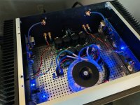
Finished up my F6, and am loving it so far! Also fully appreciating the UMS, as I simply swapped out my Aleph J boards for the freshly built F6 boards. Going to clean up some wiring, otherwise she’s done. Big thanks to 6L6 for your help along the way! And thanks to all those who made this project available, especially NP for the superb design!
Attachments
That looks great!! Well done and congratulations on another success!! 
😀 😀 😀
Yes, the UMS is very good for exactly that - once you have any of the amps built, swapping the amplifier boards into the existing chassis/PSU is easy and makes trying a complete different amplifier a bargain.
😀 😀 😀
Yes, the UMS is very good for exactly that - once you have any of the amps built, swapping the amplifier boards into the existing chassis/PSU is easy and makes trying a complete different amplifier a bargain.
As easy as popping the lid off and removing a few screws! While I’m giving thanks, you’ll notice the PSU snubbers you helped with - they’ve made a marked improvement to my ears 🙂
Well, I finally discovered why the power-on LED on the left channel board hasn't been lighting up. It turns out that the LED on the left board is connected to the V– supply. This is not shown in the schematic, and hasn't been mentioned anywhere in the F6 threads that I have read. I'm pretty sure I'm not the only one who might have been confused by this, so posting the information to help others.
- Home
- Amplifiers
- Pass Labs
- F6 Illustrated Build Guide