I have a question about my F6: it's built with 4U case, it's biased at 0.59V across R2 (25W class A output); the ambient temperature is 22°C, the max temperature taken in the hottest place on heat sink is 54°C, the temp on pin 2 of the mosfet is 62°C. I used Keratherm pad and I think is quite good the 8°C temp difference from Mosfet pin2 to heat sink but I have 32°C of temp increse from ambient on the heatsink: is it normal? Let say the dissipation on 1 channel is about 60W, being the heatsink of 4U case about 0.31°C/W I should have +20°C or so above ambient temp, about 42°C on heat sink and not 54°C!
fact is a fact
whatever is your heatsink declared , situation in vivo is ....... a fact
have you uninterrupted air flow around the case ?
whatever is your heatsink declared , situation in vivo is ....... a fact
have you uninterrupted air flow around the case ?
No, I also tried to change the positioning of the amp but the situation is almost the same. I'm going to reduce the bias, I just wanted to understand what was going on...
-Alex
Sent from my iPhone using Tapatalk
-Alex
Sent from my iPhone using Tapatalk
Isn't this what is confusing B1 v2. Papa posted it a few weeks (months) ago, here on DIYAudio
Found it.
HIFI2000 case ?
which one exactly ? 4U/300 or 4U/400 ?
4U/300 Deluxe
I believe that's what you get , when you skimp on depth of case ......... 😉
with HIFI200 cases , which are pretty good value for money (especially when you're living in Italy) , 4U/400 is right on spot for most of Papamps , and 4U/500 for those hotter ones
with HIFI200 cases , which are pretty good value for money (especially when you're living in Italy) , 4U/400 is right on spot for most of Papamps , and 4U/500 for those hotter ones
Always turn the preamp on before the amp.
As stated above the preamp was turned on for some minutes before the amp. So maybe it's a case of quality control issues with the jfets since they both failed with relatively the same service hours.
As stated above the preamp was turned on for some minutes before the amp. So maybe it's a case of quality control issues with the jfets since they both failed with relatively the same service hours.
So the preamp was always turned on before the amps? So whatever early turn on spikes should have no effect. Were the amps turned off before the preamp? Does the Aikido have output caps? Not familiar with it.
Just trying to understand this better.
So the preamp was always turned on before the amps? So whatever early turn on spikes should have no effect. Were the amps turned off before the preamp? Does the Aikido have output caps? Not familiar with it.
Just trying to understand this better.
Hi Nashbap,
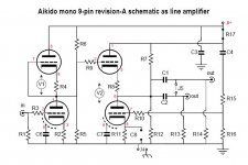
Yes always on for a minute or so before the amp was turned on, and the amp always turned off first. I've attached a pic of the Aikido line stage circuit. Like I said before I'm no expert in EE, just a hobbyist that can barely put together a previously designed kit. But my guess is that on power up of the tube line stage it takes a while for the tubes to heat up to their operating points so whacky things can happen before everything is hot and equilibrated. It looks like I need to put together a B3 preamp now.
PJN
Attachments
Hi there.
I am living in SG and we have 240 Vac during the day and up to 260 Vac (overnight, when the power grid is not loaded).
Which gives higher VDC voltage, the 18vac secondaries would be translated to 26-27VDC
Would this be too much for F6. I am thinking whether I should go for 18VAC or 15VAC secondaries to drive F6 ?
Thanks,
Oleg
Hi there.
I am living in SG and we have 240 Vac during the day and up to 260 Vac (overnight, when the power grid is not loaded).
Which gives higher VDC voltage, the 18vac secondaries would be translated to 26-27VDC
Would this be too much for F6. I am thinking whether I should go for 18VAC or 15VAC secondaries to drive F6 ?
Thanks,
Oleg
Be sure to have supply capacitors rated more then 25v, 35v should be fine.
Mind also that you will experience bias drift, so be sure to set it when you will have the higher power supply.
Thank you.
Yes I was thinking about 35v capacitors, the thing I do with all of my equipment here 🙂
So apart from bias, should I consider having more heatsinking?
Sent from my ONE A2003 using Tapatalk
Yes I was thinking about 35v capacitors, the thing I do with all of my equipment here 🙂
So apart from bias, should I consider having more heatsinking?
Sent from my ONE A2003 using Tapatalk
same here, my mains also fluctuate until 235V but never reach 260V, thats crazy spike, even your regular electronics will suffer, consider to have a good stavoltThank you.
Yes I was thinking about 35v capacitors, the thing I do with all of my equipment here 🙂
So apart from bias, should I consider having more heatsinking?
Sent from my ONE A2003 using Tapatalk
extra voltage means extra heat, but it depends on your existing heatsink temp on normal 220V mains , if less than 50°C than should be fine. otherwise you can add additional fan
Hi Gadut
Thank you for your insight.
It gets up to 260 overnight when the grid is not in use around 2-3am
It is not a spike but rather a constant state. I know that is a lot. My equipment is working good so far though. And I won't really listen the music at this time 🙂
So consider my headphone amp. Transformer carefully
For F6 and M2. I am thinking 18vac should still suffice at 240-250vac
Sent from my ONE A2003 using Tapatalk
but why??? you should have slept at that time 😀
maybe it's constant not spike, i get higher mains during holiday only.
long time ago when i had happy time with pc games rig, having a good 1kVA ups is mandatory, you can even look at the log of mains voltage history. but now i think that audio chain can absorb more voltage instead of those tiny parts in pc.
yess 18Vac should be good, if you are worry alot, you can add extra 1ohm 50W power resistor on your power supply CRC. or you can get inductor with small awg to get high Rdc 1ohm and it will be cheaper than bulky low Rdc
Hi Nashbap,
Yes always on for a minute or so before the amp was turned on, and the amp always turned off first. I've attached a pic of the Aikido line stage circuit. Like I said before I'm no expert in EE, just a hobbyist that can barely put together a previously designed kit. But my guess is that on power up of the tube line stage it takes a while for the tubes to heat up to their operating points so whacky things can happen before everything is hot and equilibrated. It looks like I need to put together a B3 preamp now.
PJN
Shelved My tube pre because it made my F6 build sound Bad.. And.. I saw it pump the driver cones..
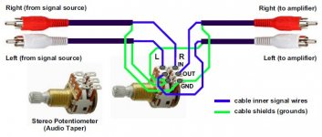
Did this; using a cheap Ebay Dact copy attenuator.. as temp measure.
It works V well for me... Likely not so temporary.
Attachments
Last edited:
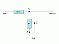
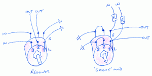
Another possibility is the "Shunt Mod"
This allows the signal to be attenuated by one resistor which can be very high quality.
(Not my invention.😉)
Shunt Pot Volume Control for Better Sound and/or Gain Reduction - World-Designs-Forum
This allows the signal to be attenuated by one resistor which can be very high quality.
(Not my invention.😉)
Shunt Pot Volume Control for Better Sound and/or Gain Reduction - World-Designs-Forum
Attachments
buy Intact audio 200$ AVC
when you get some time , put complementary JFet buffer in front of it and you're done , for good
when you get some time , put complementary JFet buffer in front of it and you're done , for good
- Home
- Amplifiers
- Pass Labs
- F6 Illustrated Build Guide