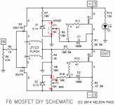
Imagine we mesuring resistance in two points 1 and 2.
Pot is 5K, so which resistance must be at OFFSET and BIAS pot, when we start amplifer first time?
Thanks!
Zen Mod
Thanks!
ColinA123
Todo: use LM over zeners 😀
Moving 2 closer to 1 increases voltage at gate relative to source thus increasing current, moving 2 to 3 decreases it.
So set them at 3 during startup and you'll be fine. Another note though is that the 5.1V zeners are low enough that even if you start them at 1 they won't conduct that much current anyway so as long as you don't let them simmer for a long time you should be fine.
one DVM across R1 or R2 , to measure Iq
second DVM from Out to GND , to measure output DC offset
start with both pots on minimum ( short between wiper and lower pin) , iteratively, few turns one then other
soon you'll get which one is for you setting Iq and which one DC ..... fact is that both are adjusting both values 🙂
second DVM from Out to GND , to measure output DC offset
start with both pots on minimum ( short between wiper and lower pin) , iteratively, few turns one then other
soon you'll get which one is for you setting Iq and which one DC ..... fact is that both are adjusting both values 🙂
One part of my bi-polar PSU not working, and i have no idea why.
Only one LED indicates that left PSU part working, also ... i see small smoke from one of diodes... and immedately turn off amplifer. What a $%()% 😡
I cut diode bridges from capacitors filter PCB and trying to swap diode bridge from working (left on picture) part to right part of PSU, but it did not help!
Also each capacitor PSU charged around 25VDC and slowly discharge, so probably no short circut inside capacitors or on PCB.
Also diode bridges when separated also working too without any issues.
Also each capacitor PCB when charged have enough power to light 36V 60W bulb for around 2 seconds...
Very strange behavour, can someone help with this!?
Attachments
Last edited:
check for shorts , there is no other explanation
orientation of parts ?
I'm not familiar with these pcbs ..... and not intending to be , considering that plenty of Greedy Boyz are ..
orientation of parts ?
I'm not familiar with these pcbs ..... and not intending to be , considering that plenty of Greedy Boyz are ..
check for shorts , there is no other explanation
orientation of parts ?
I'm not familiar with these pcbs ..... and not intending to be , considering that plenty of Greedy Boyz are ..
When i charge for 1 second left and right capacitor bank (PCB) they have much power to light 36V 60W light bulb for around 2 seconds, so probably no short circut.
Careful not to short any of your mounting washers to the rail pads.
I did this once and got the same symptoms you have.
If you have mounting washers top and bottom of pcb be careful that none of them are touching any of the rail pads (shorting to earth)
If you are shorting only one rail it will still light up bulb.
I did this once and got the same symptoms you have.
If you have mounting washers top and bottom of pcb be careful that none of them are touching any of the rail pads (shorting to earth)
If you are shorting only one rail it will still light up bulb.
Last edited:
well , you reprted that you have problem
try to be systematic , and use bulb tester
is diode bridge functional ?
is cap bank functional ( no shorts - check with buzzer on your DMM) ?
is everything oriented as prescribed ?
something is wrong ...... and as long pcbs are at your bench , only you can find where is the culprit
try to be systematic , and use bulb tester
is diode bridge functional ?
is cap bank functional ( no shorts - check with buzzer on your DMM) ?
is everything oriented as prescribed ?
something is wrong ...... and as long pcbs are at your bench , only you can find where is the culprit
Which problem may be if after diode bridge i get only 17VDC (must be AC*1.414=25.45V) and on transformer secondary 18VAC. Also i try diode bridges from Vishay and remove thermistor, but voltage after diode bridge still remains 17VDC😕
Last edited:
there will not be 1.41 without caps
voltage is pulsating in a way which DVM can't measure properly
check diodes with diode test , check caps for shorts
connect them together , power up via bulb tester
report here
voltage is pulsating in a way which DVM can't measure properly
check diodes with diode test , check caps for shorts
connect them together , power up via bulb tester
report here

I make an research, i make following decision - short in one or more caps.
Caps probably arrive damaged, because diode bridge functioning normally and everything is soldered correctly.
Also one of wire from diode bridge (600V 35A Vishay) moves when i turn on amplifer, that's because MUCH use of current - short.
Time to order new PSU PCB because i absolutely hate to desolder 😀
From the results Euvl posted keratherm performed even better than mica and goop.
I haven't personally done that comparison (mica vs keratherm) but I wouldn't doubt it. Keratherm really is that good.
Keratherm will deliver
Indeed, the package from DA store arrived today and switched them immediately - mosfet temperatures are now 25-30 degrees lower, so quite a difference. Temperature differential with heatsinks 2-5 degrees at the moment (depending on how much you trust my cheapo laser thermometer).
Interesting observation, after switching and letting the amp warm up, bias now reached just 0.38 V (it was biased to 0.5 V before). I guess that's all down to the mosfets operating at different temperatures (they were around 75-80 degrees before).
Edit: attribution 😉
Last edited:
I've been sounding off like a broken record about keratherm, even tested them to prove the point.
Zen Mod says three words, and he gets all the credit.
You bastards. It's not like I'm getting paid here.
That's it the friendhip is over.
Hahaha
Zen Mod says three words, and he gets all the credit.
You bastards. It's not like I'm getting paid here.
That's it the friendhip is over.
Hahaha
...mosfet temperatures are now 25-30 degrees lower...
Is that just from switching insulator types? Without getting into the merit of which one is best, switching between silpad, keratherm and mica + goop never results in such a big difference. I would believe differences measured in single digits only. I know because I have tested several of them, including different types of thermal compounds when using mica.
yeah. The previous ones were some that a guy from the local electronics shop sold me, so i have no idea what kind they were (there's a photo a few pages back but that doesnt help much), but they were clearly not doing their job very well...
IRFP240 datasheet - https://www.vishay.com/docs/91210/91210.pdf
K170 datasheet - http://www.mouser.com/ds/2/408/6909-57550.pdf
J74 datasheet - 2SJ74 pdf, 2SJ74 description, 2SJ74 datasheets, 2SJ74 view ::: ALLDATASHEET :::
K170 datasheet - http://www.mouser.com/ds/2/408/6909-57550.pdf
J74 datasheet - 2SJ74 pdf, 2SJ74 description, 2SJ74 datasheets, 2SJ74 view ::: ALLDATASHEET :::
- Home
- Amplifiers
- Pass Labs
- F6 Illustrated Build Guide