A quick question. If I need to mount the MOSFET on heatsink and need to run wires from MOSFETs to PCB, what is the max wire length recommended? What type/guage of wires could be used?Like Zen Mod suggested you will need one per channel and if you use the diyaudio pcb you will need to run wires from the pcb to the mosfets ie one mosfet on each heatsink.
Sent from a handheld device. Some typos may creep in
The gate wire could be 22 to 24 awg
For drain and source connection anything between 14 and 16 awg.
I couldn't tell you exact lengths but that case is small, so the lengths will be relatively short any way
For drain and source connection anything between 14 and 16 awg.
I couldn't tell you exact lengths but that case is small, so the lengths will be relatively short any way
While running wires between MOSFET and pcb, is the any chance for the wires to pick up external rf which in turn may make the signal noisy? Is it a good idea to connect shielded coax cable's center core (where shield wire will be trimmed and will not be connected) to avoid such type of external noise? Or a normal pvc shielded copper wire (like electrical wires) of 14 or 16 agw be sufficient?The gate wire could be 22 to 24 awg
For drain and source connection anything between 14 and 16 awg.
I couldn't tell you exact lengths but that case is small, so the lengths will be relatively short any way
Sent from a handheld device. Some typos may creep in
Be sure the boards fit the heatsinks and use a fan and it should work. I am like others and do not know if there will be room enough for the PS transformer and PS section so you may need to use a separate case as you said and it does not need heatsinks. I have a fan on one of my builds when I used inadequate heatsinks. A nice quiet computer fan or two is no problem for me and works wonders. ZenMod shared something called "baby sitter" (I cannot remember name for it) that works great as well.
If you have some woodworking or metalworking skills or know someone that does you can order just heatsinks from our store. You will need 2 of the 300mm X 165mm ones for $30 apiece plus shipping. Less than a $100 shipped.
http://diyaudiostore.com/collections/accessories/products/40mm-heatsinks?variant=16888345604
Last edited:
One problem with that ebay case is the inside H is only 60mm. I do not know of a power transformer that will fit. Also, the F6 pcb will not fit in that height on the heatsinks with the mosfets mounted below the pcb. I, personally, try to have as few moving parts as I can, not to mention that a fan would require another p.s. and a switch to turn it on/off. Can you find at least a 3U tall enclosure or use the DIYAudio store heat sinks only at 4U (165mm) height (which could also be predrilled and tapped)?
saik...: You can run normal wires to the mosfets for that short of length. Try to not have the wires sit on top of the power transformer (normal smart routing). Solder the gate stopper resistor onto the mosfet gate (G) pin instead of on the pcb. You can use a slight twist to twist the drain (D) and source (S) wires together, but do not twist the gate wire with them to avoid causing a parasitic oscillation (G and D might couple). You probably can go as small as 18 awg for the drain and source wires and not notice any difference.
saik...: You can run normal wires to the mosfets for that short of length. Try to not have the wires sit on top of the power transformer (normal smart routing). Solder the gate stopper resistor onto the mosfet gate (G) pin instead of on the pcb. You can use a slight twist to twist the drain (D) and source (S) wires together, but do not twist the gate wire with them to avoid causing a parasitic oscillation (G and D might couple). You probably can go as small as 18 awg for the drain and source wires and not notice any difference.
@propitious, I cannot thank you enough for explaining the technicalities behind this wiring techniques.
I've been searching over internet on this wiring techniques for quite some time. This would be a lesson for me and might be helpful for others as well.
Thanks again.
Sent from a handheld device. Some typos may creep in
Understood. Thanks.Pcb will be mounted on floor of case if that wasn't already obvious.
Sent from a handheld device. Some typos may creep in
Can someone point me to the BOM, I see no link in the DIYAudioStore nor in the buildguide?
What mosfets are Q1 & Q2, do these need to be matched as offset is adjustable, can anyone suggest where to get these?
Thanks,
What mosfets are Q1 & Q2, do these need to be matched as offset is adjustable, can anyone suggest where to get these?
Thanks,
Can someone point me to the BOM, I see no link in the DIYAudioStore nor in the buildguide?
What mosfets are Q1 & Q2, do these need to be matched as offset is adjustable, can anyone suggest where to get these?
Thanks,
Please see this post:
http://www.diyaudio.com/forums/pass-labs/277850-f6-illustrated-build-guide.html#post4406647
Not sure if there are any typos so please refer to the schematics
when in doubt.
Cheers,
Dennis
Q1, Q2 are low noise jfetsCan someone point me to the BOM, I see no link in the DIYAudioStore nor in the buildguide?
What mosfets are Q1 & Q2, do these need to be matched as offset is adjustable, can anyone suggest where to get these?
Thanks,
the specified 2SJ74, 2SK170 are obsolete but obtainable from a couple of people on here.
Replacement types are available from the store (you need B grade)
General opinion is that anything offered on E-bay is fake!
Thanks all. I hadn't spotted post #3. None matched Mosfets makes life easier. I've order the JFET's from Spencer Cheung (skcheung68@hotmail.com) before, for my F5 build.
Maybe. As you probably already know the 4U is recommended. From what other members have said it will fit and if there is a heat problem a nice quiet fan will solve that problem. Having only 2 power mosfets it should work. Some adjustment of heating can be done on the biasing. I tried using some heatsinks I had laying around on one build and found them inadequate. I put a fan inside and now it runs very cool.
Will it fit? Yes.
Is it enough heatsnk? Maybe. Probably, the F6 isn't a particularly hot amp. I think it would work, but I wouldn't promise anything, where the 4U is known to be enough. There's no such thing as too much heatsink for these amps, but you can easily have too little!
Is it enough heatsnk? Maybe. Probably, the F6 isn't a particularly hot amp. I think it would work, but I wouldn't promise anything, where the 4U is known to be enough. There's no such thing as too much heatsink for these amps, but you can easily have too little!
My first Pass amplifier - in progress
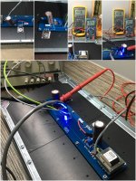
Building my first Pass amplifier - the F6. The last amp I build was a UCD than 10 years ago. Build is still in progress - I have just finished testing the F6 boards using a bench power supply. Manage to get it to bias around 600mV - still creeping up slowly as the temperature increases. I will need to fine tune it once i put them into a case. Power supply parts are still on the way, so, I have to wait 🙂
Photos attached - this is the 'simple' ac degeneration version. Boards from diyaudiostore, with SK170/SJ74/IRFP240.
Attachments
Last edited:
- Home
- Amplifiers
- Pass Labs
- F6 Illustrated Build Guide