Maybe I missed it but, do you have a path to GND at the input? Input resister? When you say "no input" do you mean nothing plugged into the input jack? I would GND or terminate the input if making noise measurements. Are we talking about an amp with typical gain? Verify the gain.

Folks:
I am considering building an F6 and would like, if possible, to use some NOS Toshiba jfets that have been in my parts drawer for years. I have matched sets of Gr and V-grade jfets (equivalent to Linear Systems' A and C grades, respectively). My 2SJ74-Gr and 2SK170-Gr jfets have an idss of 5.02 mA and the 2SJ74-V and 2SK170-V jfets have an idss of 13.4 mA.
Are either of these sets suitable for an F6 and, if so, are there any changes to the BOM that should be made to accommodate the chosen jfets?
Thanks for the counsel.
Regards,
Scott
You want to choose the lower Idss values, as you have 23V Vds across the jfet.
You want to keep the dissipation under 200mW to ensure they last for a nice long time.
No other changes required.
You want to keep the dissipation under 200mW to ensure they last for a nice long time.
No other changes required.
2picoDumbs:
Thank you! I assume "You want to keep the dissipation under 200mW to ensure they last for a nice long time" was a reference to the alternate use of the V-grade jfets and not a suggestion that I add some resistance to the Gr-grade jfets' sources.
I'm not much of a technician, so please let me know if I've just made my ignorance plain for all to see.
Regards,
Scott
The circuit works best without any source resistance on the jfets so a part with a lower Idss value without source resistors will be optimal in this application.
Re: Pico's Magic F6 Trick
Did it.
Sounds really good. Just started listening.
Could you tell us a bit more what went into your choice of MOSFETs and R1,2 values?
Do it.
Did it.
Sounds really good. Just started listening.
Could you tell us a bit more what went into your choice of MOSFETs and R1,2 values?
Did it.
Sounds really good. Just started listening.
Could you tell us a bit more what went into your choice of MOSFETs and R1,2 values?
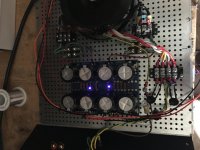
Well if you installed the green leds then you don't need 0.47 Ohms.
With 0.22 Ohms you have less heat in the resistor. Less heat equals less thermal distortion. This was an observation I made while testing resistors, some resistors were bloody terrible. The best I measured were Vishay CPF. I am sure there are also many other good choices though.
Regarding mosfets these were carefully chosen based on transconductance values to provide a certain sonic character without needing any degeneration whatsoever.
The other method is to use degeneration but that leads to some increased higher order harmonics.
The end result should be something that approaches the sound of J2 but with only a single gain stage, and is also much better into reactive loads.
In other words, it's bloody good.
Last edited:
Well if you installed the green leds then you don't need 0.47 Ohms.
With 0.22 Ohms you have less heat in the resistor. Less heat equals less thermal distortion. This was an observation I made while testing resistors, some resistors were bloody terrible.
Pico, if I go with your 3 led solution, I should change the .47’s to .22 ohms?
Just want to make sure I understand.
Thanks very much
If you are building on a fresh pcb then yes.
If you have to desolder parts, then I’ll leave it up to you to decide.
If you have to desolder parts, then I’ll leave it up to you to decide.
If you are building on a fresh pcb then yes.
If you have to desolder parts, then I’ll leave it up to you to decide.
But doesn't the choice of R1,2 of 0.56/0.47 vs 0.22/0.22 also influence the composition of harmonics, if I understood Nelson's talk correctly and also the discussion in some of the other threads (a while back, when I wasn't on this forum yet)?
So basically going degenerate (R1 == R2) de-emphasizes third harmonics, so it would result in relatively more second harmonics (or was it the other way round)? I hope to find some time to start playing with REW soon.
I do think I hear a difference in the sonic signature (aka sounds more better bloody good) after the changes, which in my case included going with 2picoDumbs' alternative mosfets.
Last edited:
So it comes down to harmonics/sound. Anybody have a preference or “feel” the sound is better one way or the other? Is there a performance, heat wise improvement one way or the other? Less heat is better I presume for long life.
Since I’m gathering parts to begin building the amp pcb’s can non-polarized 1K uf be used?
I have several Nichicon Muse in the drawer...
I have several Nichicon Muse in the drawer...
If you want to just try the lower resistance version, 'tack' a parallel resistor across the 0.47 & 0.56 power resistor (to get down to 0.22R) as a temporary measure without resorting to major removal
- Home
- Amplifiers
- Pass Labs
- F6 Illustrated Build Guide