Why not float the node between the transformer primaries? That way common mode would not depend on flux cancellation in the transformer.whatever , one pic is worth zilll.......
@ Rush :
fine 😉
when I embraced my own dumbness , it helped me in asking numerous questions without shame
however - having 4-fillar (or recently even 6-fillar) repeater , opens numerous possibilities ;
for instance - something as balanced ACA (implementing 4-fillar ) ....... where amp itself could be much greater than sum of parts , even with plain vanilla mosfets in output
@ lhquam - yes , why not ( even if hum possibilities are arising , dependable of exact physical layout of amp itself ) ...... I'm using floating windings whenever I can
Last edited:
Why not float the node between the transformer primaries? That way common mode would not depend on flux cancellation in the transformer.
One picture worth a zillion words.
Rush
where amp itself could be much greater than sum of parts
The world's first Holistic Amp?

@ Rush :
...
@ lhquam - yes , why not ( even if hum possibilities are arising , dependable of exact physical layout of amp itself ) ...... I'm using floating windings whenever I can
You can also get 2X voltage gain by paralleling the primaries with In+ and In- attached to the ends.
yup
I wrote several times about (my peasant view of ) difference between (strictly) balanced and symmetric ..... where symmetric is nothing else than balanced symmetric-ized (CT-ed) around some ref. potential
I wrote several times about (my peasant view of ) difference between (strictly) balanced and symmetric ..... where symmetric is nothing else than balanced symmetric-ized (CT-ed) around some ref. potential
for instance - something as balanced ACA (implementing 4-fillar ) ....... where amp itself could be much greater than sum of parts , even with plain vanilla mosfets in output
Que?
remind me - you got 5-fillar , or 6-fillar , or both
(and from where ) ?
as I said - I'm lazy tonight 😉
(and from where ) ?
as I said - I'm lazy tonight 😉
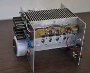
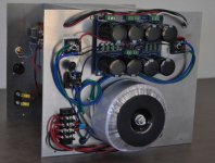
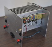
I finally got all the parts and metalwork for the prototyping chassis. The idea is to make it easy to access and interchange all of the PC boards. The boards and MOSFETs are mounted with holes conforming to the DIYAudio Universal Mounting Spec. The power supply or its transformer are easy to change. If I want to test an amplifier design with higher heat dissipation than convection cooling will allow, two PC fans can be mounted at the bottom (or top) of the heatsinks.
The photos show the chassis with the F6CC prototype boards.
The photos show the chassis with the F6CC prototype boards.
Attachments
I finally got all the parts and metalwork for the prototyping chassis. The idea is to make it easy to access and interchange all of the PC boards. The boards and MOSFETs are mounted with holes conforming to the DIYAudio Universal Mounting Spec. The power supply or its transformer are easy to change. If I want to test an amplifier design with higher heat dissipation than convection cooling will allow, two PC fans can be mounted at the bottom (or top) of the heatsinks.
The photos show the chassis with the F6CC prototype boards.
Very nice made. "IF" something goes wrong with amp...it will be very easy to work on it!😉
Very nice made. "IF" something goes wrong with amp...it will be very easy to work on it!😉
Yes. I do not really intend that this packing be used for a "finished product", but for development, testing, and listening evaluation. OTOH, it would not be difficult to add some perforated sheet metal around it to create a safe package.
Congrats for a compact, and well-thought off build. Cool!I finally got all the parts and metalwork for the prototyping chassis. The idea is to make it easy to access and interchange all of the PC boards. The boards and MOSFETs are mounted with holes conforming to the DIYAudio Universal Mounting Spec. The power supply or its transformer are easy to change. If I want to test an amplifier design with higher heat dissipation than convection cooling will allow, two PC fans can be mounted at the bottom (or top) of the heatsinks.
The photos show the chassis with the F6CC prototype boards.
hi all
just about to test my boards and realised I may have an issue with my power supplys
I am using the seletronic rcores as shown a few pages back which are 230v 300va 18/0/18
now after wiring them to my ac in which is au 240v I,m getting 22.5v out of the secondary,s ,not 18v
the thing that has me concerned is that after the power supplys im getting 61.5v dc 😱 this seems way too much considering the f6 schematis says around 23v in
I am using the aussie amps power supplys here
The PSU-Three Power Supply Module
is this ok ? why am I getting 61v after rectification ,it seems way too high
Sheafer
why am I getting 61v after rectification ,it seems way too high
That's the no-load voltage. Under load it will be lower.
hi 6l6
yes correct that is with nothing connected ,just measuring off the rails
so is this ok ? the input jfets will not be damaged ,r11/12 are jumpered so no degeneration
cheers Sheafer
yes correct that is with nothing connected ,just measuring off the rails
so is this ok ? the input jfets will not be damaged ,r11/12 are jumpered so no degeneration
cheers Sheafer
hi all
well I tested my boards today and one board is fine with 1.2v bias on both side with p1 and 2 working as intended
the other board has 26v between r7 and source and -26 on the other side
both p1 and p2 are unresponsive
both leds are lit so I presume they are the correct way around
I have tested the k170 and j74 and they are fine
I have resoldered every join with no change and checked every component to be correct twice so I,m currently at a loss
any suggestions on where to go from here
Sheafer
- Home
- Amplifiers
- Pass Labs
- F6 Amplifier