OK tested with my jfet models. No difference. Not that.
Try changing the transformer model to two separate transformers.
Try changing the transformer model to two separate transformers.
Separate transformers didn't work.
Must be something not quite right with transformer parameters.
Must be something not quite right with transformer parameters.
You asked for the circuit. You can run the sim and see for yourself.
Oreo I am very happy to finally find your error.
You have positioned source resistors incorrectly.
Source resistor must go between source of mosfet and junction of capacitor not between junction of capacitor and output.
Now you can correctly play with the circuit, and you will see our Papa's magic.
😀
Last edited:
Which models do you use?
And, speaking of input JFETs, can one use GR grade JFETs on the inputs? I can't seem to find record of this anywhere, but I am sure it must have been discussed...
Try and use Jfets with Idss between 7mA and 8mA, if you use 9mA or higher you are at risk of burning them out.
Doesn't the original F6 circuit show the capacitor connected directly to source, though?
See schematic.
That circuit is incorrect.
The correct circuit is below.
http://www.firstwatt.com/pdf/art_f6_baf.pdf
I hope they haven't copied this mistake onto the pcb. I'm going to check it now.
Last edited:
Doesn't the original F6 circuit show the capacitor connected directly to source, though?
See schematic.
Read what I said again. Source resistor should be connected between source and the junction of the capacitor. It is connected directly to source, just not like the incorrect circuit you linked
Not happy. PCB is wrong.
Nelson's F6 article is now all in vein. None of Papa's suggestions will work based on the linked circuit of 6L6 at least they don't work in simulation as discovered by Oreo.
Time for a revised F6 PCB immediately.
Can't believe this wasn't picked up earlier.
Edit: I'll be desoldering caps and doing a mod to correct it.
Last edited:
Perhaps 'wrong' is a bit strong. It is just one design choice... Reading the article you linked, it seems that connecting the cap directly to the source will result in a certain amount of 2nd harmonic in a certain phase (purposely being vague). Adding some resistance between the source and cap then affects the amount and phase of 2nd harmonic present. Amounts and phases will differ with every amp built due to part matching.
Perhaps 'wrong' is a bit strong. It is just one design choice... Reading the article you linked, it seems that connecting the cap directly to the source will result in a certain amount of 2nd harmonic in a certain phase (purposely being vague). Adding some resistance between the source and cap then affects the amount and phase of 2nd harmonic present. Amounts and phases will differ with every amp built due to part matching.
The circuit shown by 6L6 will not work with any of Nelson's suggestions as discovered by Oreo.
The circuit will work of course but not with the tweaking ability.
Oreo will confirm this observation when he has a chance to apply the correction to his circuit.
The circuit shown by 6L6 will not work with any of Nelson's suggestions as discovered by Oreo.
The circuit will work of course but not with the tweaking ability.
Oreo will confirm this observation when he has a chance to apply the correction to his circuit.
Well pico you are correct, the new sim oreo.asc is now 2nd harmonic dominant.
I was going by the .pdf schematic I put in one of my posts and as you said it is wrong. Wow, that is huge---well done by you sir. You said the DIY boards are wrong? If that is correct then I have some work to do.Man my curiosity has paid off, with your expertise of course. I hope everyone who bought DIY boards can become aware of this. How to proceed with that?
You are both assuming that the boards are wrong. The boards were designed acccording to the file loaded in the DiyAudio Store F6 thread. This is based on the F6 as released by Nelson. It is not based on the original F6 write up. The original boards allowed the degeneration to be completely or partly included in the local feedback loop using a "zen pot".
Not happy. PCB is wrong.
Nelson's F6 article is now all in vein. None of Papa's suggestions will work based on the linked circuit of 6L6 at least they don't work in simulation as discovered by Oreo.
Time for a revised F6 PCB immediately.
Is it?
The diyAudio F6 PCB was made to the schematic provided by Nelson when asked for one, specifically, this -
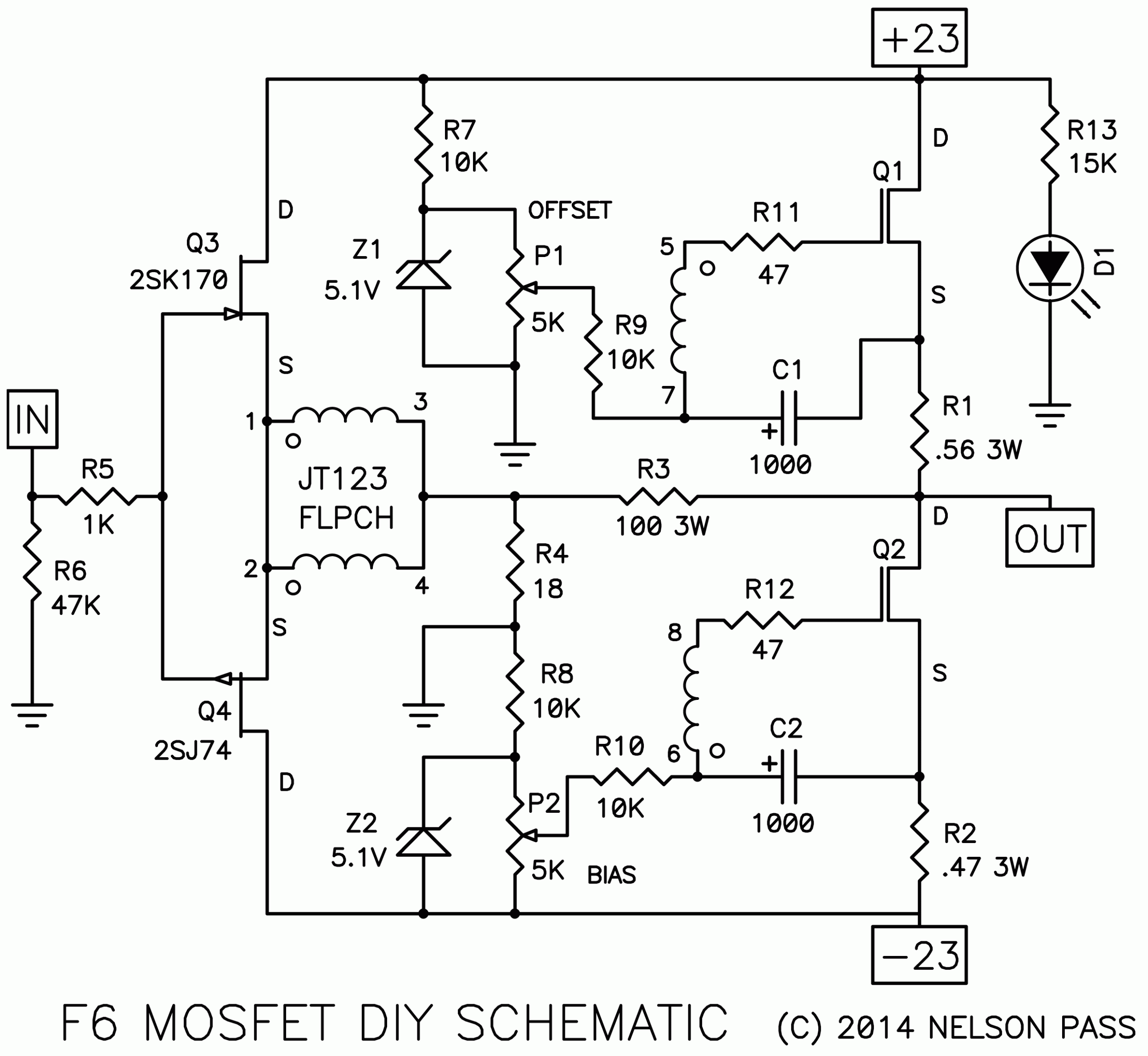
Note that the capacitor is attached directly to the source of the Mosfets.
Yes, it does differ from the "Output Degeneration" schematic from the presentation at BAF '13 -
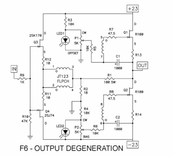
If the PCB has an error different than that, I'll happily look into it.
If one wants to connect the caps to the 'bottom' of the source resistors, a simple flying lead will be quite easy if one wants to try.
The thing I notice is the change of transitors from R100 to Mosfets so I thought this is the reason for the change of Mostfet version schematic.
If there is a problem with the F6 Mosfet version schematic I am sure Papa will let us know.
Last edited:
I had previously posted that my F6 sounded dull and lifeless as have others.Maybe we will get a better sounding machine from this.I will start my mod and report back when finished.
Forget the Zen pot that was Patrick's idea. Nelson clearly explained in the article that the harmonic distortion could be tweaked selecting different values for source. The way circuit is now that does not occur.You are both assuming that the boards are wrong. The boards were designed acccording to the file loaded in the DiyAudio Store F6 thread. This is based on the F6 as released by Nelson. It is not based on the original F6 write up. The original boards allowed the degeneration to be completely or partly included in the local feedback loop using a "zen pot".
I'm sure the amp sounds superb the way it is. It also produces very low distortion.
However I chose to build this amp based on F6 article. Nulled 2nd harmonic is not of interest to me on this occasion.
The good news is you can perform a mod to the pcb to get it like Nelson's original schematic with 0.56 and 0.47 Ohm source so that it behaves as described by Nelson in his article.
Last edited:
Yes, that is true. It is also true that the value of the cap still comes into play. You can even play with the phase of the distortion profile you select. Quite an educational amp. I would suggest the R100, personally, but to each his own.
I had previously posted that my F6 sounded dull and lifeless as have others.Maybe we will get a better sounding machine from this.I will start my mod and report back when finished.
Mine is not dull or lifeless at all if anything the complete opposite. I will agree there is something wrong somewhere if yours sounds that way.
Last edited:
- Home
- Amplifiers
- Pass Labs
- F6 Amplifier