Alazira, I don't think my speaker relays come with a diode. What value of the diode do you recommend?
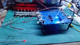
I have finally got my protection board working but I lost the 2 seconds delay when powering up the amp from the back panel on /off switch. Meaning to say, once I switch on the amp, the MR led lights up instantly. I think it should be okay since the speakers and inputs are still dis connect at this start up. I use flux to clean up the board but there are still tiny particles in between the really tiny legs of those semI conductors. What do you guys use to clean up the board?
Attachments

I believe you still have some shorted pins somewhere.
Your 3-state toggle does not seem to behave as intended.
You should clean your PCB properly using a PCB cleaner spray.
And you can remove excess solder from the SMD parts using a thin solder wick.
It helps if you use 0.3mm solder and a magnifying glass, during solder and after (for inspection).
Patrick
Magnifying glass and good lighting is crucial. I have removed all the excess particles on the board, including those in between the legs of those chips and now I have 9 seconds of delay time when powering on the amp from the back panel's switch. 3Vdc across the speaker sense shut the board down.
Last edited:
You're right, Patrick. I do believe that the excess solder particles are shorting the pins and altering it's behaviour. Can I use plastic screws (from those plastic standoffs) to mount the regulators, etc to the front panel? If I use metal screws it will connect the board to the ground.
You need to use mica insulators and insulating washers.
This is really the most basic that one should know.
https://www.reichelt.de/Heat-Transf...ICLE=8713&GROUPID=7774&artnr=IB+2&SEARCH=ib+2
https://www.reichelt.de/Heat-Transf...ex.html?ACTION=3;ARTICLE=8194;SEARCH=glimmer
Patrick
This is really the most basic that one should know.
https://www.reichelt.de/Heat-Transf...ICLE=8713&GROUPID=7774&artnr=IB+2&SEARCH=ib+2
https://www.reichelt.de/Heat-Transf...ex.html?ACTION=3;ARTICLE=8194;SEARCH=glimmer
Patrick
I have the mica insulators and have temporary mounted the board onto the front panel using the plastic screws. Thought I could use them permanently.
Plastic screws will stretch over time and lose their tension.
So metal is still better choice.
Patrick
So metal is still better choice.
Patrick
Magnifying glass and good lighting is crucial. I have removed all the excess particles on the board, including those in between the legs of those chips and now I have 9 seconds of delay time when powering on the amp from the back panel's switch. 3Vdc across the speaker sense shut the board down.
did you start F5X
Impression ?
Not yet. I'll built my power supply to bias the amp. I haven't done yet. Probably these couple of days. You did the protection board already?
Not yet. I'll built my power supply to bias the amp. I haven't done yet. Probably these couple of days.
C Reg C power supply or C R C power supply
You did the protection board already?
No. I got v3 pcb. I am not sure how to debug all Issues.
I am using the C Reg C.
With the V3 board, there are just 2 wires that you need to connect and 2 traces that you need to cut.
See post #469.
There's a pdf file to download. The details are in there.
You really need a good magnifying glass and good lighting for this very delicate fix.
With the V3 board, there are just 2 wires that you need to connect and 2 traces that you need to cut.
See post #469.
There's a pdf file to download. The details are in there.
You really need a good magnifying glass and good lighting for this very delicate fix.
Last edited:
You can see the mute and regulator relays (D4) using protective diodes. Some automotive relays have built in diodes. If they don't, you should add one somewhere.
Thanks for the pictures. I can solder the diodes for the speaker relay directly onto the legs of the relay, correct?
Attachments

Yes, the back emf diode can go across the coil pins.Thanks for the pictures. I can solder the diodes for the speaker relay directly onto the legs of the relay, correct?
Check whether the relay coil works both ways. Some are polarised and only accept +ve to a specified pin.
The relay coil I have works both ways.
As for the power supply wires, connecting from rectifier to the caps, can I use awg 18 gauge wire or should I use heavier gauge wires?
As for the power supply wires, connecting from rectifier to the caps, can I use awg 18 gauge wire or should I use heavier gauge wires?
Hopefully, not off topic.
I have 2 1st round GB F5X kit with the rev 1 protection boards. Is the rev 4 protection board available from Xen?
Thanks,
I have 2 1st round GB F5X kit with the rev 1 protection boards. Is the rev 4 protection board available from Xen?
Thanks,
In principle yes.
The problem is finding someone to dig it out from the store, pack, go to the post office and send it to you.
Easily an hour's work.
Patrick
The problem is finding someone to dig it out from the store, pack, go to the post office and send it to you.
Easily an hour's work.
Patrick
- Home
- Amplifiers
- Pass Labs
- F5X -- the EUVL Approach - The Build Thread