How much (approximately) does the bill of materials come to (without the PCB) for the protection board?
Protection Board Layout
Hi all,
Is this the correct way to connect the protection board and are the jumpers in correct position?
Thank you.
Hi all,
Is this the correct way to connect the protection board and are the jumpers in correct position?
Thank you.
Attachments


Last edited:
There seems to be a few version of this jumpers layout. Each seems to suit individual preferences.
Most are on the 'ON' position except for CB1 and CB2. Some guys have CB1 off and some have CB2 off. Is the choice of the speaker relay crucial? It seems to be the link between the amp output and the speaker binding post.
Last edited:
Hey all
Just wondering.. whats the current situation regarding avalibility of circuitboards and transistors for the F5x ? easy or hard to get hold of ? I don't have the ability to create PCB myself so...
Just wondering.. whats the current situation regarding avalibility of circuitboards and transistors for the F5x ? easy or hard to get hold of ? I don't have the ability to create PCB myself so...
anyone using F5X without protection board ?
My protection board recently failed (probably something I did when disassembling the amp to add snubbers). However, before I finished the protection board I ran the amp for almost a year without it. You can use the regulator by not installing the relay. I used pin sockets so that I could change them easily when I wasn't sure I would use 12V (in series) or 24V ones. I had also installed the mute board on the XLR output connector so those were easy to remove. I never installed the input relay so nothing to do there.
There seems to be a few version of this jumpers layout. Each seems to suit individual preferences.
CB1 = Both standby (red led) & operate (blue)
CB2 = operate mode (blue) only
All the trip and startup should be "on"
Regulator relay you want powered in both standby and operate mode so CB1="on" and CB2="off"
The Mute and speaker relays you want powered only in operate mode (and off in standby) so CB1="off" and CB2="on"
Maybe Markus has a photo of his protection board to show you.
Patrick
Unfortunately I do not have related photo in my archive. If this would be still of interest I will take one an post it. Pls let me know.
BTW. I am currently running my amp in a minimum protection configuration.
Only the mains relays and the regulators relays are implemented.
Why no speaker relays? Well, I can hardly imagine that the engergy stored in the caps could burn my speaker coils in the event of failure, nor the energy stored in the transformers would suffice. This of course has to be reconsidered when I will kick the passive x-overs out of my speakers and go for active. And the mute relays I could miss in any case. I prefer to hear the music coming up with the supply voltage and decay when switching the amp off. Reminds me to times when I was young and fiddling around with old tube radios 🙄
Markus
CB1 = Both standby (red led) & operate (blue)
CB2 = operate mode (blue) only
All the trip and startup should be "on"
Regulator relay you want powered in both standby and operate mode so CB1="on" and CB2="off"
The Mute and speaker relays you want powered only in operate mode (and off in standby) so CB1="off" and CB2="on"
Thanks, alazira. That makes a lot of sense now.
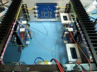
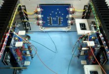
Just found one, I hope it is of help.
Markus
Thanks for the picture, Markus.
I noticed that there is a pair of wires coming out of 'sense 1' and 'sense 2' of your protection board (circled red). Where are these going? Are they coming in from the amp's output? If so, then what are the pair of wires at 'RSR' at P1 and P2 from? Also, at P4 'TRP RST', where do these wires go to? I asked because i am not sure if I am wiring up my protection board correctly.Thank you.
Attachments
Last edited:
Protection Board
The output from the main amp board should go to the 'sense 1' and 'sense 2' of the protection board at P5 and P6. And the regulator relay is to connect to the 'RSR 1' and 'RSR 2' at P1 and P2.
The output from the main amp board should go to the 'sense 1' and 'sense 2' of the protection board at P5 and P6. And the regulator relay is to connect to the 'RSR 1' and 'RSR 2' at P1 and P2.
Attachments
Last edited:
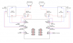
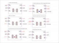
1) The outputs from the main amp boards should go to the 'sense 1' and 'sense 2' of the protection board at P5 and P6.
2) The regulator relays are to connect to the 'RSR 1' and 'RSR 2' at P1 and P2.
3) The mute relays on top of the input boards (2 tiny holes flanking the mute board relay) are to connect to the 'ISR1' and 'ISR2' at P1 and P2.
4) I still haven't figure out the 'TRP RST' connection.
5) I think the jumpers are in the correct positions now.
Can someone tell me if the polarities if the connections are correct?
Thanks.
Attachments

Last edited:
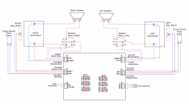
1) The outputs from the main amp boards should go to the 'sense 1' and 'sense 2' of the protection board at P5 and P6.
2) The regulator relays are to connect to the 'RSR 1' and 'RSR 2' at P1 and P2.
3) The mute relays on top of the input boards (2 tiny holes flanking the mute board relay) are to connect to the 'ISR1' and 'ISR2' at P1 and P2.
4) The 'TRP RST' is actually for shorting the pins together by installing another switch for this operation. It is only necessary after a fault is detected by the board and is 'Trip'. Switching off the mains supply for a minute will have the same effect. So, in this case, I don't think I want to install a switch just for this purpose. I'll leave it empty.
5) I think the jumpers are in the correct positions now.
Thanks.
Attachments
Pmchoong, may I suggest to study the protection board documents and the included schematics Patrick kindly provided. See post #740. I think all information is ready available.
A few remarks on your latest diagram.
1) Please be aware that all relay drivers provide 24V output voltage. Mute and reg. relays however are rated for 12V. So you should consider to drive two relais in series by one output. I remember an almost endless discussion on this subject in this thread.
2) The x-fmr input accepts AC, there are rectiviers on board. You do not need to have upfront rectification to provide DC supply.
3) The sense wiring looks like it is conneced to the amp board supply terminals (top and bottom) , this is of corse not recommended.
4) As for your earlier question. I did run the sense wires down to the speaker terminals.
A very general remark.
Do careful and thorough testing of all boards prior to integration into the housing such that you could be 100% shure all boards work according to expectation. Board troubleshooting in an integrated amp is almost impossible
See for instance my post #716.
Markus
Last edited:
> Mute and reg. relays however are rated for 12V.
I believe 24V versions are also available from Digikey.
But I also ran them in series to make sure they activate simultaneously.
Patrick
I believe 24V versions are also available from Digikey.
But I also ran them in series to make sure they activate simultaneously.
Patrick
Last edited:
Pmchoong, may I suggest to study the protection board documents and the included schematics Patrick kindly provided. See post #740. I think all information is ready available.
A few remarks on your latest diagram.
1) Please be aware that all relay drivers provide 24V output voltage. Mute and reg. relays however are rated for 12V. So you should consider to drive two relais in series by one output. I remember an almost endless discussion on this subject in this thread.
2) The x-fmr input accepts AC, there are rectiviers on board. You do not need to have upfront rectification to provide DC supply.
3) The sense wiring looks like it is conneced to the amp board supply terminals (top and bottom) , this is of corse not recommended.
4) As for your earlier question. I did run the sense wires down to the speaker terminals.
A very general remark.
Do careful and thorough testing of all boards prior to integration into the housing such that you could be 100% shure all boards work according to expectation. Board troubleshooting in an integrated amp is almost impossible
See for instance my post #716.
Markus
Thanks, Markus. Yes, I read that doc by Patrick but then I forgot that I read it.
1) 'In series' is by driving 2 boards with the same output as shown in my diagram. Correct? And yes, There were a lot of discussion and frustration too on this subject. Anyway it was settle but no one show us how it was done.
2) Yes, it is AC. I was reading about Patrick's write up on testing the board and the 15Vdc bench supply somehow stuck in the back of my mind.
3) Sorry about the confusion. It is coming out form the main amp's output.
I want to be sure of all the connections and testing of the boards before I start assemble the amp.
Anyway, I just test the protection board and it wasn't behaving as it should be. Once I swithed on the back power button, the Led of LSP2 from P5 lights up. There is some very faint light coming from the led of Lsp1 too. Then follow by the MR Led 2 or 3 seconds. When I pressed the front panel button, The Red Led of the front panel lights up only briefly. When I pressed the button again, a faint blue ligths up and all the rest of the others red LEds lights up. But the I pressed the buton again (to switch off) the red lights remain glowing but the blue light goes off. How do i trouble shoot?
Thank you.
Attachments

Pmchoong, in series means
+24 o-------12V Relays------12V Relays-----o GND
What I see in your sketch is parallel connection of relays
As for trouble shooting. There is no other way then to go along the signal path´ you look up from the schematics and see where it goes wrong on your board.
One point of attention: The protection board PCB GND should be free floating and by no means be connected to the amp GND.
I wish you success
Markus
- Home
- Amplifiers
- Pass Labs
- F5X -- the EUVL Approach - The Build Thread