pmchoong,
I did the board repair since I was part of the first batch (same as yourself). I posted a couple of photos of the finished product here.
Regarding the replacement resistor values, I exchanged a few posts with EUVL here. The repair works great, and I the DC detection/protection works as expected.
I did the board repair since I was part of the first batch (same as yourself). I posted a couple of photos of the finished product here.
Regarding the replacement resistor values, I exchanged a few posts with EUVL here. The repair works great, and I the DC detection/protection works as expected.
Really? I just clicked on them both, and they went to different locations. First link should go to post #613 showing photos of my populated and fixed protection boards. Second link should go to post #601 talking about the revised SMD resistor values.
Really? I just clicked on them both, and they went to different locations. First link should go to post #613 showing photos of my populated and fixed protection boards. Second link should go to post #601 talking about the revised SMD resistor values.
Works as advertised for me. Many thanks for the update and info Horio.
This symptom has something to do with the preference of number of posts per page. The link uses the page number based on Greg's preference. The software doesn't always convert to the correct page with the reader's preference.
Ala,
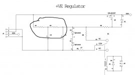
what current flows through each of those resistors?
Then determine the dissipation.
Compare that dissipation to Pmax. Aim for <<50%, preferably <10%
what current flows through each of those resistors?
Then determine the dissipation.
Compare that dissipation to Pmax. Aim for <<50%, preferably <10%
Say at start up C2 is empty (0V).
R1 sees full rail voltage (say 22V when not loaded)
In the second or so when C2 (and later C3) gets charged, R1 sees :
22*22/1k = 484mW.
Yes, only for a second or so.
But why take any risk ?
Patrick
R1 sees full rail voltage (say 22V when not loaded)
In the second or so when C2 (and later C3) gets charged, R1 sees :
22*22/1k = 484mW.
Yes, only for a second or so.
But why take any risk ?
Patrick
Say at start up C2 is empty (0V).
R1 sees full rail voltage (say 22V when not loaded)
In the second or so when C2 (and later C3) gets charged, R1 sees :
22*22/1k = 484mW.
Yes, only for a second or so.
But why take any risk ?
Patrick
Thanks Patrick,
I have some PRP 0.1% 10ppm, but then I find that they are 1/10W, not the usual 1/4W ones. In any case, looking at your calculation, perhaps I will use 1/2W ones, even if only for psychological comfort 🙂
It is not in the signal path, so just use any decent 2x7mm metal film.
Vishay Dale CMF55 or Vishay Beyschlag MBB0207 1%, e.g., are rated at 0.4W.
I think the PRP 0.5W may be too large to fit PCB.
Patrick
Vishay Dale CMF55 or Vishay Beyschlag MBB0207 1%, e.g., are rated at 0.4W.
I think the PRP 0.5W may be too large to fit PCB.
Patrick
Hi,
i have some parts for the f5x at home and want do build one. I have a few 2sj74 with Idss between 5.4 and 6.4 mA und a few 2sk170 with Idss between 7 and 11 mA. Can i degenerate the 2sk170 instead of the 2sj74? Is it a good option?
Many thanks for your help!
Daniel
i have some parts for the f5x at home and want do build one. I have a few 2sj74 with Idss between 5.4 and 6.4 mA und a few 2sk170 with Idss between 7 and 11 mA. Can i degenerate the 2sk170 instead of the 2sj74? Is it a good option?
Many thanks for your help!
Daniel
If you degenerate the 2SK170, you will be able to match the bias current, but at the expense of more imbalance in open loop gain.
As discussed before, they might cancel out to a more or less extent in the balanced configuration.
But I would at least try to get some 2SK170GR first.
They are not difficult to get, and in the worst case you can try LSK170A.
Patrick
As discussed before, they might cancel out to a more or less extent in the balanced configuration.
But I would at least try to get some 2SK170GR first.
They are not difficult to get, and in the worst case you can try LSK170A.
Patrick
I’m ready to apply power to my protection board. I’ve read the test procedure, I don’t have a lab supply (yet, will do for the amp boards) I assume it’s ok to test with the auxiliary 15VA 2 X 12V transformer?
Thanks Patrick.
Alexis thanks for your kind offer, I should be ok with the fuse solution Patrick suggests for the protection board, next month I plan to invest in the lab supply to bring up the amp boards.
Alexis thanks for your kind offer, I should be ok with the fuse solution Patrick suggests for the protection board, next month I plan to invest in the lab supply to bring up the amp boards.
Ouch, I was hoping to do so, and then I looked at the price for an appropriately sized set of PSUs, not cheap. I hope you know what you're getting yourself into there.

Rechecked my work, I cannot find fault on the untested board. Should I start increasing the fuse rating, around 150mA?
- Home
- Amplifiers
- Pass Labs
- F5X -- the EUVL Approach - The Build Thread