It was okay when I bias the amp individually and test the protection board separately. It is only when both these are integrated, the problem starts.
Substitute for 2SK3497 and 2SJ618
After a looong wait I'm about to build the F5X.
I'm looking for 2SK3497 and 2SJ618 for the Power Supply, but they are not easy to find now. I prefer to by things from DigiKey and found two Mosfet that looks ok on the paper. FQA28N15 and FQA36P15-ND.
Does any one have a better choice?
--Per Eklund
After a looong wait I'm about to build the F5X.
I'm looking for 2SK3497 and 2SJ618 for the Power Supply, but they are not easy to find now. I prefer to by things from DigiKey and found two Mosfet that looks ok on the paper. FQA28N15 and FQA36P15-ND.
Does any one have a better choice?
--Per Eklund
They both drop >4V at 4A bias, so you loose voltage headroom.
You should look for something with Vgs ~2.5V at 4A, and Yfs >> 2S.
Patrick
You should look for something with Vgs ~2.5V at 4A, and Yfs >> 2S.
Patrick
I didn't find any thing with right spec at DigiKey so I ended up bying 2SJ200/2SK1529 from eBay. They are very similar to the original.
--Per
--Per
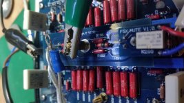
The R101 is burned. In my haste to get the amp up and running, I've connected the v (-) filter board wrongly. The rest seems okay. I've test the board with lab supply and it still work. Will this affect the biasing?
Attachments
Last edited:
You should check through all the DC voltages (across MPC74's and at the output).
If they remain normal, then you got lucky and nothing is damaged.
Patrick
If they remain normal, then you got lucky and nothing is damaged.
Patrick
The voltage across all the mosfets are the same as before. I'll change the resistors with the same value ones.
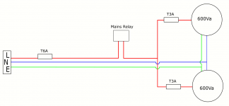
If you use separate fuses for each Tx, then IMHO no need for T6A.
And you will always need a separate one for the AUX Tx.
Patrick
And you will always need a separate one for the AUX Tx.
Patrick
if you use a mains relay with two sets of contacts (DPST), you can use one set of contacts to bypass the added resistor (soft start) for one transformer and use the other contacts for the other bypass.
I've changed the burned resistors and reconnected all wires and it's singging beautifully now. Thank you everyone, especially, Patrick for making this worthwhile.
But the dc offset value is different. I don't know if it's the new resistors I replaced. It is now at 18mv for the left channel and -10mv for the right. Do the input resistors affect the dc output? If this is so, then I'll have to re bias the amp again.
It should not, but then 18mV is also nothing for a power amp.
You can always fine adjust again.
Happy for you,
Patrick
You can always fine adjust again.
Happy for you,
Patrick
Thank you very much. It's a beautifully sounding amp. I'm glad that I did it. I'll fine tune it again. Right now I just want to listen to it.
glad you did It
congratulations
Thank you. You should build yours.
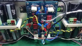
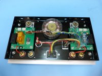
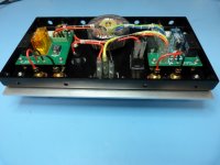
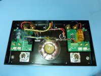
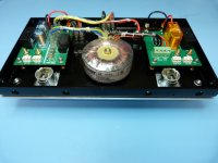
Backplane connectivity
Since we were under the impression that the rather wild wire routing and loosely mounted components at the backside of our first amp would not be an adequate permanent solution we designed two backplane boards ...
Markus & Ulrich
Since we were under the impression that the rather wild wire routing and loosely mounted components at the backside of our first amp would not be an adequate permanent solution we designed two backplane boards ...
Markus & Ulrich
Attachments
- Home
- Amplifiers
- Pass Labs
- F5X -- the EUVL Approach - The Build Thread