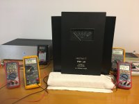
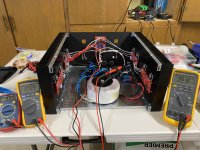
After starting on this project 3 1/2 years ago, I finished setting the bias on one mono block. Bias and DC offset adjustments using the two FE boards and 2 - P1's and 2 - P2's. Next is adjusting P3 using REW, since it will output 1 watt, I can adjust the VU meter to read 1 watt at the same time as the P3 adjustments. Separate enclosure for the power supply, 48.1V rails (enclosure to the left in the photos), heat sinks at 44'C in the middle. The front panel uses 3M double side foam tape.
I'm going to have engraved plates with PASSDIY to cover the FIRSTWATT engraving.
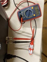
My only concern is the DC offset is .351v when I first power the amp up, it drops as the bias stabilizes. I may power the amps up with no speakers connected for the first 1/2 hour, turn the amp off, connect the speakers and then power up again.
I'm going to have engraved plates with PASSDIY to cover the FIRSTWATT engraving.
My only concern is the DC offset is .351v when I first power the amp up, it drops as the bias stabilizes. I may power the amps up with no speakers connected for the first 1/2 hour, turn the amp off, connect the speakers and then power up again.
Attachments

Nice build.
How quickly does the DC offset drop from its value of 0.351V at startup? Note 0.351V corresponds to less than 0.008 W into 8 ohms, so hopefully it won't be a problem for you in actual use.
How quickly does the DC offset drop from its value of 0.351V at startup? Note 0.351V corresponds to less than 0.008 W into 8 ohms, so hopefully it won't be a problem for you in actual use.
My desoldering gun is one of my most invaluable assets.Hopefully the removal of the mosfets won't be too much of a problem.
Cheers,
Dennis
Swapping the mosfets did the trick, as I’m up and running now. I haven’t played with the bias or offset yet, so I have no idea if any damage was done.
I will continue to post updates and questions, but thanks for the help thus far.
Attachments

About a half hour before it settles to 6 mV. 0.008 w doesn't sound as bad as .351v. I'll run it with my work shop speakers while I dial in the next mono block. I'm hoping the second will be faster to adjust than the first since I've learned so much setting the bias on the first, it's the DC offset which is so hard to dial in with four adjustments.How quickly does the DC offset drop from its value of 0.351V at startup? Note 0.351V corresponds to less than 0.008 W into 8 ohms, so hopefully it won't be a problem for you in actual use.
Had I known how difficult it is to adjust, I wouldn't have built a Balanced version.
What desoldering gun did you purchase? They are not inexpensive and I'd rather not make a mistake buying one.
I have the hakko FR301 and don’t regret it. It’s expensive but has proven invaluable for someone as mistake prone as me. I’ve had it for about 6 months and believe it’s paid for itselfWhat desoldering gun did you purchase? They are not inexpensive and I'd rather not make a mistake buying one.

That is what I am aiming for. Thank you so much, and to you too, Dennis, for your feedback.I have the hakko FR301 and don’t regret it. It’s expensive but has proven invaluable for someone as mistake prone as me. I’ve had it for about 6 months and believe it’s paid for itself
i do fear that that the mosfets are gone. at lest some of them. as this are grouped, ya you guest it.
Also. make sure your TH1 and TH2 are only tuching the plastic og the irf prts. (one for pch and one for N ch for each ch). Not the washer. And skip the diodes.What desoldering gun did you purchase? They are not inexpensive and I'd rather not make a mistake buying one.
Hi all,
just want to confirm I’m setting the bias/offset correctly for the monos. I’m using post 2 of this thread as a guide.
I have 3 DMM:
N channel: TP2/3
P channel: TP2/3
Speaker out
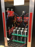
I’ve brought the offset up to ~88mv using alternating 360 turns on P1/2 of the FE board. I’m hearing an audible buzz at the moment from the transformer, which concerns me.
just want to confirm I’m setting the bias/offset correctly for the monos. I’m using post 2 of this thread as a guide.
I have 3 DMM:
N channel: TP2/3
P channel: TP2/3
Speaker out
I’ve brought the offset up to ~88mv using alternating 360 turns on P1/2 of the FE board. I’m hearing an audible buzz at the moment from the transformer, which concerns me.
Attachments


Your transformer may be reacting to "apparent" DC on the incoming AC line. If it goes away tomorrow, then it almost certainly is DC. If the buzz is constant, then it may be that you did not tighten the central mounting bolt firmly enough, or that you forgot to use the damping pad provided by the transformer manufacturer. Sometimes buzzing can be further dampened by adding additional isolation (e.g., sorbothane or isodamp) between the transformer and the chassis floor and the transformer and the upper mounting plate.I’m hearing an audible buzz at the moment from the transformer, which concerns me.
If you have DC on your line, then consider Rod Elliot's DC blocker design.
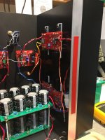
I have a DC blocker, but that didn’t solve the buzz issue; however, when I swapped out my PSU board, the buzz went away.
something’s wrong with one of my PSU’s, causing the transformer to buzz.
good news is that I’m able to start biasing one of the amps.
something’s wrong with one of my PSU’s, causing the transformer to buzz.
good news is that I’m able to start biasing one of the amps.
Attachments
Hello edwinjones4,
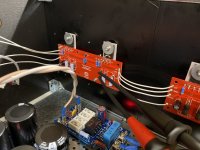
your measured values on the DMMs look very good. Around 2-3 mV DC-offset at speakerout is really good.
Will have to be readjusted (slightly) if all is in a case.
MosFets have survived and seem to be matched very well (N-ch to P-ch).
Cheers
Dirk 🙂
your measured values on the DMMs look very good. Around 2-3 mV DC-offset at speakerout is really good.
Will have to be readjusted (slightly) if all is in a case.
MosFets have survived and seem to be matched very well (N-ch to P-ch).
Cheers
Dirk 🙂
Thanks Dirk. I cheated with the mosfets and swapped them out with new ones, which seem to be matched well.Hello edwinjones4,
your measured values on the DMMs look very good. Around 2-3 mV DC-offset at speakerout is really good.
Will have to be readjusted (slightly) if all is in a case.
MosFets have survived and seem to be matched very well (N-ch to P-ch).
Cheers
Dirk 🙂
still cooking but am happy with the results thus far.
not sure how to diagnose the buzz on the other PSU, but that’s a problem for another day.
Attachments
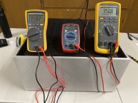
Looks like my setup. It's helpful to keep 3 or 4 voltmeters top top of new amp.

Looks like I’m in good company 😉Looks like my setup. It's helpful to keep 3 or 4 voltmeters top top of new amp.
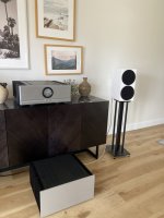
Just played the inaugural CD and it sounds great. only problem is I’m running out of real estate in the living room.
Attachments
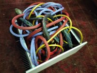
Just about to embark on a F5 Turbo V2, my third Pass amp buuild thanks to DIYAudio. Have just mocked up the case to check for fit and any additional holes and taping required. Also planning to wire it with audiophile grade cable so have fitted this as well. A couple of questions: do they make a 6U case to fit in the extra cable and how do I get the snake oil out of the system?
Attachments
and, again, ZM is Your Savior
stack two 5U cases, and there is plenty of space

stack two 5U cases, and there is plenty of space
Hello Steve Duffy,
I will call your F5 Turbo 2 the 'Medusa-amp'. Oily snakes coming out of the top-lid...
Dangerous! 😵
Cheers
Dirk 😉
I will call your F5 Turbo 2 the 'Medusa-amp'. Oily snakes coming out of the top-lid...
Dangerous! 😵
Cheers
Dirk 😉
- Home
- Amplifiers
- Pass Labs
- F5Turbo Illustrated Build Guide