Not for monoblock. N‘s on one sink p‘s on other. Also, halauhula, here are the words of 6L6 in post #1.
“Before power up, dial pots P1 and P2 to 0 ohms ( check with ohmmeter across TP1-2 and TP3-4 on FE board )”
“Before power up, dial pots P1 and P2 to 0 ohms ( check with ohmmeter across TP1-2 and TP3-4 on FE board )”
Yeah, my bad. Thank you again.Not for monoblock. N‘s on one sink p‘s on other. Also, halauhula, here are the words of 6L6 in post #1.
“Before power up, dial pots P1 and P2 to 0 ohms ( check with ohmmeter across TP1-2 and TP3-4 on FE board )”
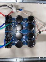
He has the two N channel boards wired together and the two P channel boards wired together. It should be one N and one P output each channel.
Yeah, my bad. Thank you again.
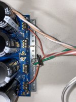
I removed the thermal paste and replaced old keratherm with new sheets. Thermistors we’re touching but I pulled them forward anyway.Do you have heat sink compound between the mosfet and insulator and then again between the insulator and heat sink? The gray paste? If so, the whole point of keratherm and such silicone insulators is that you don’t need compound or anything else. In fact it would be detrimental. Also notice that your thermistors are touching steel washer. Quite a few posts about bending thermistor inward to only touch plastic housing of mosfet else risk a short.
tested P1 and P2 using dmm across tp1-2 and tp3-4 respectively and can confirm both are at lowest levels (~1.2ohms each)Put ohmmeter probes on tp1 and tp2 on fe board and then again on tp3 and tp4. Confirm lowest possible reading and it will tell you if pots turned for minimum reading. Elwood625 it Looks like the gates and o/p are properly wired unless I’m missing something.
I used a DMM to check continuity from V+ on PSU to V+ on FE…same for V-Make sure you didn’t accidentally invert +v and -v from ps to fe board. They are same color so can’t tell. Also check that no wire or resistor leads extend below board so that it touches heat sink. Anodized aluminum not great conductor but could happen.
Also, if it was a short then the light bulb test would indicate that…I assume.
The fact that the light doesn’t illuminate but fuses blow and resistors smoke indicate a different issue, correct?
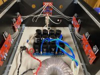
Earlier, I accidentally swapped the secondary pairs on my transformer during the build of my PSU and it caused the light to turn on.
The fact that the light doesn’t illuminate but fuses blow and resistors smoke indicate a different issue, correct?
Earlier, I accidentally swapped the secondary pairs on my transformer during the build of my PSU and it caused the light to turn on.
The “optional” resistors on ps board should be filled. put more 0.47 ohm in each spot. Also, thermistor should be like a “C”, with one end being the two soldered leads and other end tip of thermistor in physical contact with plastic housing of mosfet. Be careful not to have bare leads touching each other after bending. However, neither of these two things would be responsible for your issues. i would suggest checking all resistor values. Also, are the fets from reliable source? Matched? perhaps someone else can chime in with suggestions?
Alright thank you. I’ll update and post results.
I bought the mosfets from the diyaudio store (f5 kit), so I assume they’re legit.
I bought the mosfets from the diyaudio store (f5 kit), so I assume they’re legit.
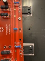
Really, I did read the F5 and original F5 turbo articles and went through many of the posts, but it is har to keep track, hence the creation of my "cheat sheet." Another Q that may relate to the failure of edwinjones4's build: are should insulating washers needed to insulate the M3 screws/bolts from the case of the MOSFETS? Otherwise it seems that there could be a short from MOSFET supply to ground.
hole in IRFP ( and similar) mosfet case is surrounded with ceramics, so no need for screw insulators of any sort
Thank you.I probably should have looked at the data sheets. I am going to be more diligent in the future.
@ItsAllInMyHead
I saw this in my email but not in the thread so I copied it:
“Rather than a "shotgun" approach -
1) Looks like you've verified +- 34V rails. 🙂
2) What wattage bulb in your DBT? If resistors immediately went up in flames, I'd assume pretty high (at or above 100W)”
It’s a 150W light bulb.
I saw this in my email but not in the thread so I copied it:
“Rather than a "shotgun" approach -
1) Looks like you've verified +- 34V rails. 🙂
2) What wattage bulb in your DBT? If resistors immediately went up in flames, I'd assume pretty high (at or above 100W)”
It’s a 150W light bulb.
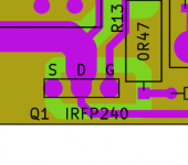
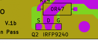
A total shot in the dark: Any chance of an N-channel and P-channel parts mix up? (The part numbers on the outputs are not visible because of the mounting washers.)
The devices on the N-channel output board should be IRFP240, and IRFP9240 for the P-channel board.
The devices on the N-channel output board should be IRFP240, and IRFP9240 for the P-channel board.

I’ll shamelessly blame the mistake on the lack of instructions 😉Don't feel too bad -- swapping the two output transistors is a relatively common mistake. Even on the M2x boards, which attempt to warn you "CHECK THE OUTPUT TRANSISTOR PART NUMBER AND BE SURE IT IS THIS STRING OF CHARACTERS"
_
- Home
- Amplifiers
- Pass Labs
- F5Turbo Illustrated Build Guide