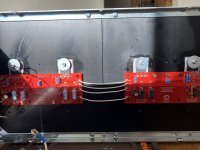
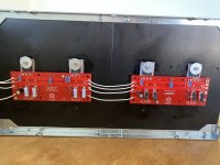
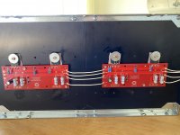
Thanks. I loosened the screws, gave the heat sinks a squeeze and refastened them. I don’t see a gap anymore.Ideally each of the 4 devices will see the same current and will be the same temp on the sinks. You're using one as "the representative" of the bunch.
tl;dr - I don't think it will matter, but I'd also like to have one more person chime in to be sure that I'm correct.
You currently have a gap between your sinks. It may close up at final assembly. You can (optionally) squish a little thermal compound between them for better thermal transfer if you want to go 'overboard'.
Attachments
Both good advices.Reference my pics in post 1435. My fe board is above the iec inlet and both my amps are deathly quiet. As long as you are about an inch above, should not be a problem. Also, most logical place since you want To be as far away from tranny as possible. Wire routing will be more important. One thing I did differently, which may give you another option, is that the +/-V and ground wires on my build connect to output boards directly from ps. This also allows those wires to be draped low in the chassis and away from binding posts and ac.
Almost everybody recommending ditching the diodes, wondering why Nelson is using them and why they are still in the schematics 🙂Would also recommend ditching the diodes. I was really hung up on this until better minds convinced me the amps are more stable without. i left them out and can confirm these things are dynamic as hell without them. Unless you have some really unique load, I don’t think you will miss them and increases your chances of successful build dramatically.
Wondering as well why there are virtually no balanced mono blocks. Having 4 output boards just add a 2nd FE-board and do full balanced. Less output power (is it not enough?) but higher voltage swing. Adding a balanced source is not the end of world (in case you only have SE) but improves every other detail.
An excellent reason for you to learn PCB layout! Now you can create a balanced monobloc amp board from whichever First Watt starting point tickles you the most. Both you, and the diyAudio membership as a whole, will enjoy the benefits.
The F5T can be wired for balanced and Nelson describes how in his paper. By buying two sets of boards from the diyaudio store for the mono blocks you get all the boards you need and if you do not ditch the 2nd FE-board per mono block, you can wire them for balanced. Everything is already available.An excellent reason for you to learn PCB layout! Now you can create a balanced monobloc amp board from whichever First Watt starting point tickles you the most. Both you, and the diyAudio membership as a whole, will enjoy the benefits.
But if you want to design your own PCBs, then well, you can learn layout, fair enough.
Last edited:
Nice and how it should be done!Thanks. I loosened the screws, gave the heat sinks a squeeze and refastened them. I don’t see a gap anymore.
I would not have put any grease between the sinks in order to "close" gaps.
^ Sorry if my post wasn't clear to you. The thermal paste's useful property is not to close a gap of that size. It's to potentially improve thermal transfer once the gap is already closed. I should have been more specific, but the person for which the message was intended understood.
Yes, he understood, to re-tighten the sinks and make it properly.^ Sorry if my post wasn't clear to you. The thermal paste's useful property is not to close a gap of that size. It's to potentially improve thermal transfer once the gap is already closed. I should have been more specific, but the person for which the message was intended understood.
Never seen grease between sink modules on commercial amps.
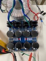
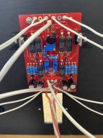
Well, I hooked everything up, included a dim bulb tester and turned on the power. Smoke immediately billows from R17-R20 and R21-R24 on p and N channels respectively, then fuse blows.
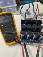
I tested the power supply beforehand and it works and measures well.
Any ideas what I’ve wired or stuffed incorrectly?
I tested the power supply beforehand and it works and measures well.
Any ideas what I’ve wired or stuffed incorrectly?
Attachments
-
 F2FE7A8E-F1B9-4A79-B6ED-3034CE517F57.jpeg516.5 KB · Views: 131
 -
 1C4EBD54-71CB-464D-A73F-D172EDDD13D6.jpeg525.9 KB · Views: 130
 -
 AB1F4885-0E57-4266-AC53-64861349E945.jpeg472.8 KB · Views: 137
 -
 6DA54BCE-4733-4251-92CD-F8EB3C2D6B3C.jpeg429.6 KB · Views: 137
 -
 EAB412D3-FE7A-4821-925F-89B86CD0059D.jpeg464 KB · Views: 136
 -
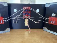 image.jpg418 KB · Views: 137
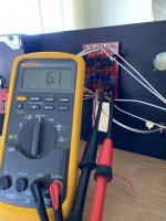
Not having built this, but remembering the set-up instructions, did you adjust the pots adjusting bias to minimum resistance per this text in the original F5 article:
Before applying power to the ampli!er, you must set the values of P1 and P2 to their minimum. Verify this with an ohmmeter.
I'd always assumed that this would mean having the pot turned full CW, and that the measurement was from the wiper to pot terminal connected to R13 was zero, but more experienced builders could advise (I was going to ask this question later - I do not recall seeing this discussed in the various threads but there are SO MANY posts to read....
Do you have heat sink compound between the mosfet and insulator and then again between the insulator and heat sink? The gray paste? If so, the whole point of keratherm and such silicone insulators is that you don’t need compound or anything else. In fact it would be detrimental. Also notice that your thermistors are touching steel washer. Quite a few posts about bending thermistor inward to only touch plastic housing of mosfet else risk a short.
Pots work in opposite direction. You have the arrows correctly marked for increasing bias, so turning against the arrow until click heard will get you to minimum.
Make sure you didn’t accidentally invert +v and -v from ps to fe board. They are same color so can’t tell. Also check that no wire or resistor leads extend below board so that it touches heat sink. Anodized aluminum not great conductor but could happen.
Just reread your note on pots. If you set them to lowest reading before inserting on board, you have essentially turned one of them all the way up because they work opposite directions. There is a post earlier how to test their resistance in situ, and that’s how to truly verify lowest setting
There is a P channel gate and a N channel gate wire from the FE board. You have the P and N channel gates wired together on the output boards.
I will try searching again but I was not able to find a post that provided specific directions. Probably my poor search skills.Just reread your note on pots. If you set them to lowest reading before inserting on board, you have essentially turned one of them all the way up because they work opposite directions. There is a post earlier how to test their resistance in situ, and that’s how to truly verify lowest setting
Put ohmmeter probes on tp1 and tp2 on fe board and then again on tp3 and tp4. Confirm lowest possible reading and it will tell you if pots turned for minimum reading. Elwood625 it Looks like the gates and o/p are properly wired unless I’m missing something.
Just copied this to my F5 cheat sheet.Put ohmmeter probes on tp1 and tp2 on fe board and then again on tp3 and tp4. Confirm lowest possible reading and it will tell you if pots turned for minimum reading. Elwood625 it Looks like the gates and o/p are properly wired unless I’m missing something.
- Home
- Amplifiers
- Pass Labs
- F5Turbo Illustrated Build Guide