

The resistors are R5 and R6. Since you are already getting some bias you shouldn't need to increase them too much. Going from 1k to 2k should be plenty. The exact value is not important so use whatever you have handy.
Also after making the change and before power up, you need to turn the bias pots back down before starting the bias process again from the beginning. You can verify this by measuring the resistances across R5 and R6, which should be close to zero when P1 and P2 are set correctly.
Also after making the change and before power up, you need to turn the bias pots back down before starting the bias process again from the beginning. You can verify this by measuring the resistances across R5 and R6, which should be close to zero when P1 and P2 are set correctly.
if you have themshould i just change the jfets to higher idss
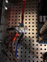
crooner2264 - I noticed in your first picture that the thermistor is not touching the plastic body of the MOSFET. They need to touch in order to control temperature of the device, do not let it touch the metal fender washer, it could short out.
Building the 5ft2 turbo with cascade and 32v rails I used r25&26 as 10k and 28&27 as 4.75k. Do I need to change r 25 & 26 to 4.75?
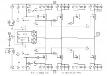
Try to restate this better. Building the F5T v2 with 32 volts DC at the rails and cascoding with Q7 and Q8. R27 and R28 are installed at 4.75k, R25 and R26 are installed at 10k. This gives me 10.3 volts at the base of Q7 and Q8. Further reading tells me I should have between 12 and 15 volts. Should I change these resistors and if so what is a recommended value with +/- 32 volts dc at the rails. At this value what size fuse should I use at the AC input
Finished my f5turbo v2 with coscode. Biased at 350 MV. Temp around 50c on heat sinks ran r25 thru 28 all at 4.75k. Had to change r5 & 6 to 2.7k to bring bias all the way up. Thanks to all on the post for guidance and the DIY store my matching transistors kept my biasing difference within 5mv. Testing right now on the open back manzanita and it controls these very well
crooner2264 - I noticed in your first picture that the thermistor is not touching the plastic body of the MOSFET. They need to touch in order to control temperature of the device, do not let it touch the metal fender washer, it could sh
Finished the turbo and seems to sound well enough. the bias on the left channel is off by 5mv ..do not know if thats normal?....I was thinking of omitting the diodes. what would have to be done? just remove them? ...also would this allow me to run higher bias?
Yes.I was thinking of omitting the diodes. what would have to be done? just remove them?
Yes, watch the heat sink temperatures when increasing the bias.would this allow me to run higher bias?
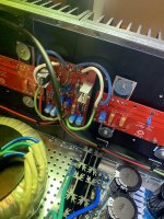
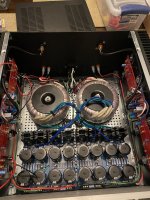
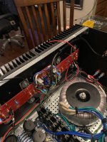
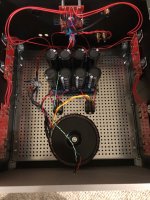
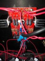
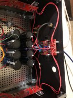
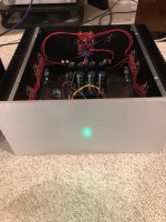
OMG! Finally finished building my monoblock f5turbo v3‘s and they are amazing!! First, I want to thank many of you for help along the way, 6L6, Zenmod, Itsallinmyhead, and others. It takes time and effort to reply to questions on the forum, so thank you. Second, some details. Each monobloc is identical, including lengths of wiring. I didn’t want any imbalance in sound. I used Avel Linberg 625va transformer with 35v+35v secondaries. Caps are Cornell Dublier 63v 18mfd using diyaudiostore power boards. I would have preferred 22 or 33 mfd, but there is no supply at any of the major stores (digikey, mouser, Newark) unless you want to pay $25-35 per cap. For monoblocks, that’s 16 caps and a lot of dough. I used IXYS hexfred bridges. These are soft recovery, sound really nice and have very low Vf drop. Also used DHLabs silver sonic 14 ga hookup wire for everything except input wire which is small length of shielded mogami. This combination sounds real nice. The solder holes on all boards are tiny and really my only criticism. 6L6‘s suggestion to cut few strands away and butt up the wire to solder pad is a good one, and is something I’ve been doing for a long time in such situations. It does unfortunately add a lot to build time. With nothing hooked up to powerboard, I measured 56vdc rails, with everything hooked up but no bias, I got 50.4vdc, and fully biased, my rails are 46.5. Perfect. Both my amps are dead quiet, and I mean dead quiet. Even with my ear up against tweeters or woofers, there is nothing - like the things aren’t powered on. only noise is a little bit of mechanical hum/buzz from the transformers which you really have to remove the top plates to hear. This is probably due to slightly undersized xfrmer but hard to find quality one with correct secondary. I used mainly bom recommended parts. For the mains/transformer interface, I used eurostyle terminal blocks. Having the standard open barrier strips exposes a major safety hazard if prying hands get into the case. When viewing my pix below, you will notice that most electrical hazard points are insulated from casual brush against. That’s not to say you can’t find places to touch that will fry you if not careful, but at least most casual contact accidents might be avoided. You only need 3 terminals to follow Nelson’s turbo power supply schematic. and now some pics. When ordering led, take note of mcd spec. Didn’t realize these are 1500mcd and even with 10k dropping resistor, they are blinding.
Attachments
-
 3F1514F7-EFE1-4A11-B448-DA6E78AB3623.jpeg548.4 KB · Views: 174
 -
 1D7BC4B9-1F80-4553-92EE-6BC7FE7453A0.jpeg452 KB · Views: 188
 -
 B08032F5-043B-4010-A968-E1497B45501A.jpeg507 KB · Views: 158
 -
 04940C18-1127-4F16-B24C-AB779DC7677E.jpeg505.5 KB · Views: 176
 -
 29280959-7B50-42F4-BDA2-ED54F7D5C113.jpeg501.5 KB · Views: 169
i have a few questions if someone can help. What is considered full bias for a 4pr mosfet v3 monoblock, 46v rails in 5u chassis? When I get to about 380mv, the heat sinks are Hot. I can only keep my hands on for about 5 seconds before I have to let go. I thought 460 was the target, but in passively cooled 5u with 4pr mosfet build, I don’t see how. Am I missing something? 2. I notice that the heatsink with output board closest to the fe board (mounted on back panel) is hotter than farther heatsink/board (closer to faceplate). the board closer to fe is one that contains thermistor and yes, they are all touching mosfet plastic housing. . Temp difference is noticeable and exists on both n and p side. Normal? Finally my one monoblock has 5mv bias difference n vs p side with <5mv offset. Pretty awesome. The other one has 29mv difference with +/- 5mv offset. I read that up to 50mv difference is acceptable but the ocd perfectionist in me is tempted to pull every source resistor and measure (I only checked resistors for correct value when stuffing board - did not pay much attention beyond that). Am I overreacting? Would you accept this difference in Your build? Thanks for any input!
Forgot to mention - no diodes in my build, only one thermistor per n side and p side (not sure I was clear)
Hello algg,
I have built my F5T-Monoblocks with railvoltages around +- 42.7 V. I have 4 N- and 4 P-channel Mosfets
per Monoblock.
I can't bias higher than 330mV- 340 mV (over the resistor) per Mosfet. I have a 500mm deep case with 210mm high x 500mm deep heatsinks on each side of the Monoblock. If I go higher in bias, then heatsinks go over 52° C after 30 minutes.
My experience.
Cheers
Dirk
Dirk, that actually is very helpful. It tells me I am overbiased because 5 u chassis is 210 x 400mm. Of course, if your chassis is something other than diyaudiostore version, our fin dimensions may be different but this is very helpful. I only have about 10 hours of music on the amps and I would expect bias to drift slightly up during break-in, so I will back off some. or may look into small fans. Could cut hole in floor amp stands and mount small noctua fans underneath stand to blow up on fins. Need to think and make some decisions. The amps sound so good I’m inclined not to mess with them. Ty
Alex
Alex
- Home
- Amplifiers
- Pass Labs
- F5Turbo Illustrated Build Guide