These amps seem to be even more finicky than my F5. Adjusting the bias is okay but the dc offset jumps from +12mv to -12mv with just the slightest touch. Getting it near 0mv has proved impossible. After hours (and hours) of playing around with it I got it at about +4-5mv.
Is there is a way to get the dc offset adjustment less erratic/finicky? For instance, if I know the approximate value needed for R5/P1 and R6/P2 to get .350mv bias and approximately 4mv dc offset, would changing the values of R5 and R6 so that P1 and P2 could be reduced to 1K pots (with same number of turns) result in less erratic results from P1 and P2 adjustments? Or even removing P1 altogether (with appropriate R5 value) and then just using P2 to fine tune the dc offset?
Is there is a way to get the dc offset adjustment less erratic/finicky? For instance, if I know the approximate value needed for R5/P1 and R6/P2 to get .350mv bias and approximately 4mv dc offset, would changing the values of R5 and R6 so that P1 and P2 could be reduced to 1K pots (with same number of turns) result in less erratic results from P1 and P2 adjustments? Or even removing P1 altogether (with appropriate R5 value) and then just using P2 to fine tune the dc offset?
I found it twitchy as hell too... I finally let it get good and hot adjusted it then just ignored it. I have no idea where it's at now, there is a slight hum when you get your ear stuffed in the speakers, but I gave it to a friend for Christmas and his speakers are less efficient, I can't hear anything. There comes a point where you need to just let that sh!t go and enjoy the music.
If your offset is below 50mV you are doing really quite well and don't worry about it.
I not so concerned about the actual DC offset level but more the amount of time it takes to adjust (I am not a patient person). Anyway, I swapped P2 with a 1K pot and R6 with a 2K2 resistor. Problem solved. I can now adjust very easily and precisely.
I’m about to tackle one of these builds. Non cascade with a 24-24V 600va ltransformer and 88000 per rail.
I’m ordering parts now but my big questions are about the diode bridges. I normally use monolithic bridges on my Pass builds but see that the included PSU board diode bridges are recommended.
What part is everyone using? Can I use the FEP30DP (TO-3P) or MBR20200CT (TO-220)?
Also, are the CL-60 utilized the same? 2 for the primaries and one for the ground?
2 for the primaries and one for the ground?
Hi, sorry for the question, but how should the CL60 be connected to the transformer primary? And what is its role in the PS scheme? Is it there only for safety reasons or could it avoid ground loop issues?
Thank you,
Gaetano.
there's just been a big discussion involving this here. Look at the last few pages:
diyAudio Power Supply Circuit Board v3 illustrated build guide
diyAudio Power Supply Circuit Board v3 illustrated build guide
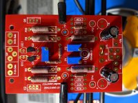
I just stuffed the FE board for a F5 Turbo v2.
Could someone have a look and let me know if it all looks ok before I solder?
P3 set to 100 ohms (half way point). P1 and P2 set to 0 ohm.
Working on the output boards now. Build guide to follow.
Thanks
Could someone have a look and let me know if it all looks ok before I solder?
P3 set to 100 ohms (half way point). P1 and P2 set to 0 ohm.
Working on the output boards now. Build guide to follow.
Thanks
Attachments
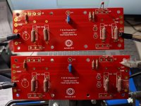
Here's the N-channel board. It seems pretty simple.
I added C3 and C4 per 6L6 recommendation, however, from the photos, it didn't look like he had them in??
Also, on the FE boards (my previous post) for the new layout, it looks like Q5 and Q6 are now Q7 and Q8. Should those diodes have a jumper between their emitter & collector?
I added C3 and C4 per 6L6 recommendation, however, from the photos, it didn't look like he had them in??
Also, on the FE boards (my previous post) for the new layout, it looks like Q5 and Q6 are now Q7 and Q8. Should those diodes have a jumper between their emitter & collector?
Attachments
I just finished an F5 turbo V2 with 32V secondaries and non-cascode.. I realized after reading a few more comments that most people used 50V Caps in the PSU and I thought I saw somewhere some builders used 35V.
Well.. I went with 35V and now wondering if this would be a problem. I only have 3 hours on the amp. Any input is appreciated.
Well.. I went with 35V and now wondering if this would be a problem. I only have 3 hours on the amp. Any input is appreciated.
32vac will rectify into 44.8vdc. Subtract 0.7v twice for two diode drops and your capacitors will see 43.4vdc constantly.
You tell me if 35v is enough.
You tell me if 35v is enough.
Also might want to seriously consider cascoding, as the max rated voltage of the Jfets is 25v. Toshibas take the excess a bit better than the LS, but in both cases the P-channel gets stressed more easily than the N.
I used Toshiba JFETs. Is it still recommended to cascode or would I run into problems?
To cascode, I would just have to pull the middle Frontend boards and add the 6 extra resistors, the 2 extra caps, and the 2sa1837 transistors. Is that correct?
To cascode, I would just have to pull the middle Frontend boards and add the 6 extra resistors, the 2 extra caps, and the 2sa1837 transistors. Is that correct?
I would also suggest cascoding since the extra voltage also means extra
dissipation for the jfets.
dissipation for the jfets.
I just finished an F5 turbo V2 with 32V secondaries and non-cascode.. I realized after reading a few more comments that most people used 50V Caps in the PSU and I thought I saw somewhere some builders used 35V.
Well.. I went with 35V and now wondering if this would be a problem. I only have 3 hours on the amp. Any input is appreciated.
Don't you meen you have +/-32Vdc rails?
Non cascode and +/-40+Vdc would likely frie the J-fets.
Annyway, i would cascode those J-fets. Let them se about 12-15V.
Last edited:
Wow. I’m sorry. I made a typo.
I have 24V secondaries with +-32V rails with Toshiba JFETs. I used the AN-6224.
I removed the 35V power caps today and will order 50V after I confirm I don’t need to cascode.
I have 24V secondaries with +-32V rails with Toshiba JFETs. I used the AN-6224.
I removed the 35V power caps today and will order 50V after I confirm I don’t need to cascode.
- Home
- Amplifiers
- Pass Labs
- F5Turbo Illustrated Build Guide