Thank you very much for that, extremely helpful. 🙂Yes, start at zero Ohms. The jfet sets the current (its idss) which produces a voltage across the resistance of P1/P2. That voltage biases the mosfet into conduction. Ex. At 500R, a 6mA jfet would put 3 volts on the mosfet gate.

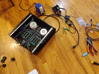
Last night I finished wiring up the my amp and used my newly built dim bulb tester to turn the amp on with the trim pots turned to the left. The light bulb stayed on as I had reversed the leads coming out of the rectifier bridge to the power supply PCB. Once I made the change, light bulb went on and off so I think I am okay to continue with setting this up. (I am guessing that the $28 spent to build the dim bulb tester has already paid off based upon my very careless wiring error. Thanks @birdbox!!!)
I do have some questions on adjusting the trim pots. I understand where I need to connect my two multimeters and just picked up two sets of mini grabbers. My F5M is stock from the current kit being offered at the DIY Store. I am also using the Deluxe 4U chassis. That means that within the range as outlined in Mr. Pass' White Paper I should be looking for 1.1 amps or .52V at R6 or R7? If I have that correct, what I am I looking for on the multimeter attached to the speaker outputs? Lastly, is there an order to which of the two trim pots I start turning? @roboDNA already provided guidance on this, but I am not sure I follow it.
Sorry if these are basic questions, but my only similar bias experience was with the Amp Camp Amp which is a far simpler amp to adjust.
YesThat means that within the range as outlined in Mr. Pass' White Paper I should be looking for 1.1 amps or .52V at R6 or R7?
No order, but start very slowly turning each of them. Little bit up on one... little bit up on the other. When the DMMs start to indicate a voltage (when the MOSFETs turn on), an increase in one will start to increase the other. That will affect the DC offset at the outputs below... which you'll quickly notice how to affect using the balance between the two.Lastly, is there an order to which of the two trim pots I start turning? @roboDNA already provided guidance on this, but I am not sure I follow it.
Go slowly, very slowly, and you will not have an issue. If you get too high, just back off a little.
<10mV is wonderful.If I have that correct, what I am I looking for on the multimeter attached to the speaker outputs?
Note - this all needs to be at temp equilibrium. Get it roughed in, then put the lid on... wait for it to stabilize, remove the lid .... tiny tweak... lid back on...
Wash, rinse, repeat.
Edited to add - this happens AFTER you've done a DBT check for each channel connected; and then removed the DBT. Don't bias the amp with the DBT connected. 🙂
Last edited:
I’ll add my 2nok, which will either make things clearer or further muddy the waters. Hopefully the former.
You can start your bias procedure with DBT connected to get a feel for it to have that extra safety net if you’re unsure. But stop well short of your final bias number and connect straight to the mains. Say shoot for about .1 or .2volts across one of the source resistors and see if you can get a feel for how you keep the offset low.
To be 100% sure to not mess things up you should dial back down the bias before shutting down and taking the DBT out.
Looking at the board, the pot on the side where the V+ connect will when cranked up increase bias and send the offset positive. Cranking up the pot on the V- side will increase bias and send the offset toward negative.
Since the boards are not mirrored this pot position will be opposite on the left and right side.
I connected my meter across the source resistors closest to the front of the amp on both boards since access was best there. That means connecting across the V- source resistor on the right board and to get positive readings on the meter, black probe closest to V- and the red probe on the other side of that same resistor. The opposite goes for the left side board. I guess it doesn’t really matter if there’s a negative number on the dmm measuring bias, but it is one less thing to mess with my head.
Lars.
While interesting to me and not necessary, I use a third meter across the pot to watch the gate voltage.
It may also be helpful after you have the bias roughed in to leave your meters attached with the cover on playing music and watch for the bias drifting too high over several hours. Mine had a tendency to drift too high (.75-.80) as the ambient temp in the room increased (South Florida) and I pushed the amp a little. The sinks never exceeded 138 F, but I didn't feel comfortable with bias much over .66 v fully warmed.
Just thinking about tube amplifiers and their common need to adjust bias whenever the tubes are swapped or the moon changes phase.
Many tube amps implement a meter, a switch and externally accessible pot ( via a knob ) to adjust the bias of the tubes.
Why don't the FIY amps implement something like that? It could be two meters in the front panel with two knobs and a switch. The meters could be used to adjust the bias or monitor the power (via the switch) and the knobs would be the pots... It could be done in a standardized board that fits into a standard cutout into the front panel.
I mean, it would add like 30 bucks to the bill of materials.... 80 if you went with some of those nice old fashioned Bakelite round meters...
Then the power supply... again, something calling for its own box. Notice how there is little room on the front panel to install the switch behind the doughnut? If the power supply was independent, it could be made to be dual mono, with two doughnuts.. there would be lots of room to have two doughnust, the soft start board, the regulators and all the caps... Perhaps with a voltage control so it could drive different OPs.
Again, just thinking... looking at how the F6 chassis was reused for the F5m... the layout seems so familiar...
And, then of course, you got the stand alone FE. If it had a volume control, you wouldn't need a preamp at all.
Last edited:
Why don't
search for a pair of SIT-1 monoblocks, pay and you have it
^ I think you missed my point....
The idea is to implement this full time on the front panel of the OP box... make it into a standardized design. Could be an option, but it were standard based it could be reused, see?
The idea is to implement this full time on the front panel of the OP box... make it into a standardized design. Could be an option, but it were standard based it could be reused, see?
^ I think you missed my point....
I think you missed mine
Say that you buy 500$ worth Kiradashi knife
Suddenly you get an idea to write to involved, well known Japanese Artisan, you having an idea of implementing every possible thingie from biggest Swiss Knife .......
A. he will ignore you
B. he will politely reply that he isn't able to do that, from various lacking technological reasons
C. he will politely reply that in possible format isn't possible to implement that, majority of customer's not asking or expecting that
D. he will politely reply that in possible format isn't possible to implement that, technical context not allowing that, even if he's completely able to do the same in some different technical context
F. he will politely reply - **** off, you stupid Gaijin
choose your option; personally, I was given with enough of F, after some time I started thinking that maybe they all are not so funny, maybe funny is on my side

now, as you're technical person .................. you certainly know better than Mighty ZM what range of reasons/reasoning is involved in design of commercial product
so, solution is simple - buzz Pa (email please, he's not responding to mobile buzz), and ask him how much Geld you need to add, to get personalized iteration of regular FW project
after that, you can only expect that your e-mail addy is added in block list titled "ZM and other Idiots"

I was interpreting "FIY amps" as DIY not FW.
If DIY was intended, then anything goes up to and including the limits of ones imagination, abilities and pocket. However, if the intent was to sponsor some sort of standardised faceplate for a chassis then you could petition the DIYAudiostore. And/or possibly get together with the people who have started numerous threads with similar chassis ideas:
"Pass DIY front panels"
"Universal outboard power chassis for Pass"
"Universal chassis"
However, for some the varied form factor is part of the fascination and IMO Nelson Brock's Redux kits are an excellent example.
I hope I got this correct, but I think one can verify that R8 and R9 are at their desired minimal values prior to initial power up as follows: Adjust the trimmer R8 such that the measured resistance across A1 and B1 is low (ideally close to zero) and do the same for R9 (across A2 and B2). These points should be readily accessible for attaching your multimeter test leads.

Thanks for that - I missed that one in my searching. I received my 4 turn pots today, and chucked them in a breadboard just now to confirm. Sure enough, CCW turns the resistance up, not down. Dennis's post #2265 plus a breadboard and a multimeter are well worth the time for anyone not ordering the trimmer from the BOM. Takes seconds.Two fires,
Take a look a post 2265. Remember reverse pinout.

(yes I know the information is in the datasheet, but what with some showing the pinout on the bottom of the trimmer and others showing the PCB layout, I didn't want to trust to being 'pretty sure' of my ability to manipulate objects three-dimensionally in my head 😅)
Oh, that's also super helpful for a post-soldering & mounting triple check. I'll be doing that. Thanks!I hope I got this correct, but I think one can verify that R8 and R9 are at their desired minimal values prior to initial power up as follows: Adjust the trimmer R8 such that the measured resistance across A1 and B1 is low (ideally close to zero) and do the same for R9 (across A2 and B2). These points should be readily accessible for attaching your multimeter test leads.
You can order from modushop and have custom holes cut no problem.I was interpreting "FIY amps" as DIY not FW.
If DIY was intended, then anything goes up to and including the limits of ones imagination, abilities and pocket. However, if the intent was to sponsor some sort of standardised faceplate for a chassis then you could petition the DIYAudiostore. And/or possibly get together with the people who have started numerous threads with similar chassis ideas:
"Pass DIY front panels"
"Universal outboard power chassis for Pass"
"Universal chassis"
However, for some the varied form factor is part of the fascination and IMO Nelson Brock's Redux kits are an excellent example.

I don't know what possessed me, it was sitting on floor and I just lit in. I'm 69 so
I have to stand and stretch occasionally!
Normally, I have a roller cart I build them on, but it has XA 252 being repaired on it, other work table has a pizza oven on it right now. Even dining room table is full with balanced Iron Pre.....considerably larger chassis than single ended version.
Good thing I live by myself!
Russellc
I had purchased two F5m kits, two transformers and 400Deluxe cases and have built one of them. I'm trying to decide if I should build the second one and parallel the amps. I originally was going to use each one as bi-amps to feed some by-amp klipsh but the super lintons I ended up getting intead don't have bi-amp inputs.
Is anyone using the parallel configuration and does it affect the sound quality in a negative way? I don't know enough to understand how to test for anomalies, if it will add a '3rd harmonic' and if that is bad. ( can it be eliminated with careful bias tuning or matching jfets/mosfets between each amp board? )
If there is any info. on how to parallel the F5m it would be helpful. AI has been my friend but it keeps apologizing for making 'mistakes'. I realize I'll have to match components, but not sure if there are any other pitfalls to this config. Thanks y'all.
- Home
- Amplifiers
- Pass Labs
- F5m kit