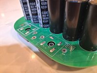
Finishing final wiring on my dual mono F5m, and have noted the other builds pics and didn't see where they had grounded the power supply to chassis.
The schematic shows a ground and maybe the pics didn't illustrate that particular feature. I did note the clipped tail of a wire coming up from underneath soldered to a ground pad on board, but couldn't see where it went.
I also noticed what looks like perhaps one of the legs of the power supply board is grounded? Haven't read any posts here in regard.
I generally ground power supply boards through a CL 60 to chassis floor. Then I started looking closer at power supply board, which has several thermistor pieces, but other than the tail through the one ground pad in a member's post, didn't see where anyone had obviously grounded theirs...I'm sure they did somewhere, right?
Thanks,
Russellc
Last edited:
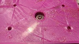
You are correct that if you use metal standoffs, the F5m PSU board has the chassis ground and thermister "built in".

If you used plastic standoffs, or just want extra feel good factor, then use a wire from that chassis ground point to chassis.
I'll also note that if you stick with the metal standoff route for chassis ground, I'd be sure to use a locking washer, or nut, on both top/bottom of the standoff connections, so it can't loosen.

Whichever method you use, make sure you have a good connection by scraping away any insulating material such as paint or anodizing on the chassis.
Whoops, I tried to post and somehow sent it as a "report" ! Folks here figured out my boobery.You are correct that if you use metal standoffs, the F5m PSU board has the chassis ground and thermister "built in".
View attachment 1401409
If you used plastic standoffs, or just want extra feel good factor, then use a wire from that chassis ground point to chassis.
I'll also note that if you stick with the metal standoff route for chassis ground, I'd be sure to use a locking washer, or nut, on both top/bottom of the standoff connections, so it can't loosen.
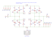
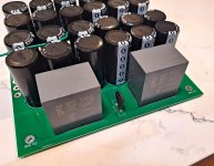
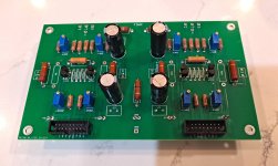
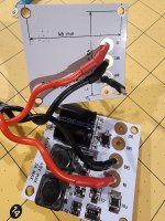
I have been working on a bridged F5m which I am calling the F5mX. It is pretty much a F5m that is bridged plus a few things. It has CCS resistors on the OS stage which give it a small single ended class A envelope. They are oriented on opposite rails on the opposing phases to hopefully break the symmetry and give a little 2HD.
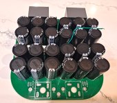
The PSU has the bridge rectifiers integrated in the board and also 70uF film caps on bypassing the last stage of the CRC cap bank. The caps are 24x10,000uF 35v. Ground lift is on the board and connects through the standoff.
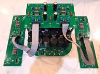
The front end connects to the output stage with a ribbon cable. I bought the ribbon cables and sockets from Amazon. I did have to shorten them. Each channel on the front end pulls it's power supply form the output stage via the ribbon cables and GND from the PSU.
The outputs are two pairs of IRFP140/9140 (one per phase) and the front end takes one quad of j74/k170 Toshiba JFETs per channel. There are spots for 4 pairs of output devices per channel.
I have had it biased at about 50-60 watts of class and have tested it up to 115 watts. The transformer that I am using is a 22vac 800va which is giving me around 26.5vdc rails. Antek has no problem making them.
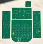
It is a pretty simple design. I initially wired the output stage point to point and tried a bunch of different things and landed on this arrangement. It is fun to play with the amount of output devices, the amount of feedback etc.
I will be ordering boards to post up on the forums. 🙂 Let me know if you are interested so I can gauge how many to order.
The PSU has the bridge rectifiers integrated in the board and also 70uF film caps on bypassing the last stage of the CRC cap bank. The caps are 24x10,000uF 35v. Ground lift is on the board and connects through the standoff.
The front end connects to the output stage with a ribbon cable. I bought the ribbon cables and sockets from Amazon. I did have to shorten them. Each channel on the front end pulls it's power supply form the output stage via the ribbon cables and GND from the PSU.
The outputs are two pairs of IRFP140/9140 (one per phase) and the front end takes one quad of j74/k170 Toshiba JFETs per channel. There are spots for 4 pairs of output devices per channel.
I have had it biased at about 50-60 watts of class and have tested it up to 115 watts. The transformer that I am using is a 22vac 800va which is giving me around 26.5vdc rails. Antek has no problem making them.
It is a pretty simple design. I initially wired the output stage point to point and tried a bunch of different things and landed on this arrangement. It is fun to play with the amount of output devices, the amount of feedback etc.
I will be ordering boards to post up on the forums. 🙂 Let me know if you are interested so I can gauge how many to order.
Attachments
-
 1735780147272.png128.4 KB · Views: 171
 -
 1735780042714.png130.2 KB · Views: 196
 -
 20241231_145425.jpg597 KB · Views: 202
 -
 20241231_141722.jpg570.4 KB · Views: 187
 -
 20241230_192741.jpg527.8 KB · Views: 167
 -
 20241230_190108.jpg416.2 KB · Views: 146
 -
 20241230_190102.jpg585.7 KB · Views: 148
 -
 20241230_101925.jpg800 KB · Views: 146
 -
 20241230_231044.jpg547.2 KB · Views: 145
 -
 20241230_213911.jpg384.3 KB · Views: 174
So I am in MN and want to build another amp. I have an essentials F5m kit, but not all the parts to complete. I'm curious if I can make do with the parts I have on hand and learn a little about the circuit at the same time....
The only parts I'm missing are the 2W resistors. Instead of 270R/2W (R3 & R4) as called for in the schematic, I have 220 ohm/3W. Instead of the 22 ohm/2W I could parallel two 47R/3W and get pretty close. I have all the other parts.

This would be installed in a 2U/300 chassis, so I'd be running on the low side of suggested bias.
What would I need to consider if using 220R/2W instead of the 270R/3W? Bad idea, or perhaps just not optimal?
Another "rigged" option is I could put each 220 ohm in series with a 47 ohm, and that's close enough to 270R. A furthermore option is I have 10R/5W, which I could figure out how to put in series with the two 220 ohms in parallel, and get darn close to the 135R (2x 270R in parallel) at 130R (2x 220R // and 1x 10R in series). I have options so just trying to understand how the circuit works and where there may be a little wiggle room, if any.
Feel free to tell me to not try any of these options if I should just skip it and twiddle my thumbs instead or building another amp
The only parts I'm missing are the 2W resistors. Instead of 270R/2W (R3 & R4) as called for in the schematic, I have 220 ohm/3W. Instead of the 22 ohm/2W I could parallel two 47R/3W and get pretty close. I have all the other parts.
This would be installed in a 2U/300 chassis, so I'd be running on the low side of suggested bias.
What would I need to consider if using 220R/2W instead of the 270R/3W? Bad idea, or perhaps just not optimal?
Another "rigged" option is I could put each 220 ohm in series with a 47 ohm, and that's close enough to 270R. A furthermore option is I have 10R/5W, which I could figure out how to put in series with the two 220 ohms in parallel, and get darn close to the 135R (2x 270R in parallel) at 130R (2x 220R // and 1x 10R in series). I have options so just trying to understand how the circuit works and where there may be a little wiggle room, if any.
Feel free to tell me to not try any of these options if I should just skip it and twiddle my thumbs instead or building another amp
The amount of feedback alteres the sound. With the 220 ohm resistors in place of a pair of 270 ohm resistors, you will end up with less gain and a sound that starts to lean away from the f5m and more towards the F5.
I believe having less feedback is part of what gives the f5m that spacious open Sound. In fact, I would suggest playing with different feedback levels and seeing what you think.
I believe having less feedback is part of what gives the f5m that spacious open Sound. In fact, I would suggest playing with different feedback levels and seeing what you think.
Thanks @Mikerodrig27 !
Since this amp will likely be handed over to a brother as a gift, I'll stay as true as I can to the original design and just make a 267R resistor by putting the 220R and 47R in series. They'll just stand tall and vertical on the PCB and I'll move on to the hard part....wiring it all up and drilling/tapping the chassis. They measure at basically 270R in series anyway.

I suspect 23R is close enough to 22R to work without issues.

I'll play around with feedback in the future when I'm home in WA and can really devote some listening time with a "tweaked" amp in a bigger chassis.
Apologies for spoolin' up about nothing. Hope I'll get this singing in the next few days. I'll report back when I do.
Since this amp will likely be handed over to a brother as a gift, I'll stay as true as I can to the original design and just make a 267R resistor by putting the 220R and 47R in series. They'll just stand tall and vertical on the PCB and I'll move on to the hard part....wiring it all up and drilling/tapping the chassis. They measure at basically 270R in series anyway.
I suspect 23R is close enough to 22R to work without issues.
I'll play around with feedback in the future when I'm home in WA and can really devote some listening time with a "tweaked" amp in a bigger chassis.
Apologies for spoolin' up about nothing. Hope I'll get this singing in the next few days. I'll report back when I do.
Last edited:
Does the F5m prefer the input to be pre-amplified? Is line level too low? What input voltage should I aim for? It's a good problem to have, but I"m now looking into making sure I'm feeding the best voltage level into it.
I"m currently sending unbalanced line-level from my focusrite DAC and have to turn up the volume quite a bit. I'm thinking the amp may expect higher than line level. When I use my soundcraft analog mixer's ( with its gain ) it sounds louder but don't want to get to the point of clipping the amp. ( how do I know when it's clipping without having to rely on my hearing? )
I"m currently sending unbalanced line-level from my focusrite DAC and have to turn up the volume quite a bit. I'm thinking the amp may expect higher than line level. When I use my soundcraft analog mixer's ( with its gain ) it sounds louder but don't want to get to the point of clipping the amp. ( how do I know when it's clipping without having to rely on my hearing? )
My 2 cents: if you can: 1. get to full volume without using preamp; 2. any output transformers in your source are not overloading (most consumer sources do not have transformers in audio output); 3. your source can properly drive your F5m in terms of impedance; and 4. the noise floor of the source when driving your F5m to the max volume that you need is low enough so you do not hear it; and the level control on your source uses a stepped attenuator, motor-controlled potentiometer or other high quality attenuation means; then it seems better not to have a preamp if accuracy is paramount.
Your scope and a sine wave. With 2 channels you can determine the input and output voltage at clipping
A typical (resistive or digital) volume control will "sound better" living @ 2 or 3 o'clock (turned up), as compared to one living @ 8 or 9 o'clock (turned down). "Better" meaning improved resolution and detail subjectively. Lots of excess system gain means you will be using your volume control "barely cracked open", meaning throwing lots of "un-wanted / un-desired" signal away to ground. This is not desirable. If it sounds good, it's good. Don't add extra system gain unless it's truly needed. There are some good "gain structure" articles and postings around.. worth searching out..
Does the F5m prefer the input to be pre-amplified? Is line level too low? What input voltage should I aim for? It's a good problem to have, but I"m now looking into making sure I'm feeding the best voltage level into it.
I"m currently sending unbalanced line-level from my focusrite DAC and have to turn up the volume quite a bit. I'm thinking the amp may expect higher than line level. When I use my soundcraft analog mixer's ( with its gain ) it sounds louder but don't want to get to the point of clipping the amp. ( how do I know when it's clipping without having to rely on my hearing? )
If built per the schematic, the F5m has about 16.5 dB of gain. 1 volt in gives 6.7 volts out. Clipping will occur around 40 Vpk-pk with 24V rails. By the math, that's 6 Vpk-pk input to clip. If the input happens to be a sinewave, that would give 2.12 VRMS
I think most of the Focusrite gear is capable of greater than 6 Vpk-pk output at full volume (so no additional preamp required) but check your specific model.
The focusrite scarlett 2i2 does have +10dbu which I believe is 2.4V but that is balanced and I"m converting to unbalanced RCA so not 100% sure the voltage is still 2.4V in that case. It does seem to be 'loud enough' at 2 or 3 oclock and I don't think I would want to listen to them louder so I guess I'll leave the pre-amp out of the path for now. I was worried the focusrite would distort but I think it's good to almost full volume.
I can also only use my analog mixer instead of the focusrite to add some extra pizz-azz but I don't see a need for that since it's loud enough at 3oclock on the focusrite. I know that fellow Deadmau5 uses large genelecs ( with sand in the walls? ) but says it's a bit of a waste since the ear adjusts to louder after a few minutes so 85-90dB is the loudest I want. I noticed this is true when I turn up to 2oclock for a few minutes then turn volume back down. ( ear has adjusted for louder sound which is bad for hearing in the long run, making gain even less justified I guess ) It's also plenty loud to get to 'feel' the really low and mid bass and that is the only reason I would want it 'louder'.
I'll get a decimal meter on my iPad to see how loud it is.
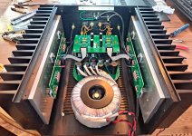
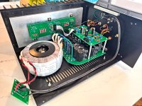
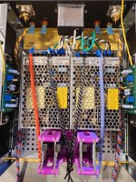
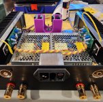
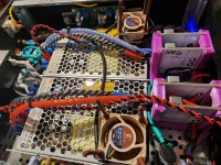
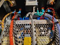
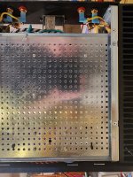
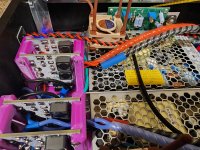
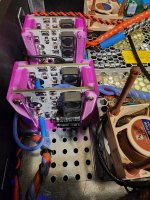
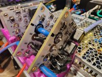
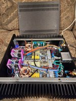
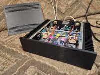
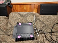
Finished up an F5m using two Meanwell SMPS LRS-150-24 PSU's with 4qty AmyAlice filters in a Modushop 2U/300. Yep, you guessed it, it sounds glorious!
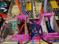
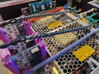
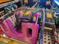
Here's a few pics of the build for funsies. I added two Noctura 24V fans as added protection as this will be a gift for a family member who knows nothing about class A amps, so I just wanted the feel good factor of additional forced convective cooling. Biased to 1.1A per Nelson's article with 0.50VDC across the 0.47R resistor(s). I created a 3D printed "AmyAlice Rack" to hold the four filters and used this wiring scheme for star grounding. If you notice the odd resistor configuration, I didn't have the 270R and 22R 2W resistors, so I made due with what I had (220R+47R 3W in series for R3 & R4 and 2x 47R in parallel for R5).

Here's a few pics of the build for funsies. I added two Noctura 24V fans as added protection as this will be a gift for a family member who knows nothing about class A amps, so I just wanted the feel good factor of additional forced convective cooling. Biased to 1.1A per Nelson's article with 0.50VDC across the 0.47R resistor(s). I created a 3D printed "AmyAlice Rack" to hold the four filters and used this wiring scheme for star grounding. If you notice the odd resistor configuration, I didn't have the 270R and 22R 2W resistors, so I made due with what I had (220R+47R 3W in series for R3 & R4 and 2x 47R in parallel for R5).
Attachments
-
 20250105_190101.jpg677.7 KB · Views: 121
 -
 20250105_140409.jpg702.3 KB · Views: 105
 -
 20250105_140356.jpg632.3 KB · Views: 105
 -
 20250105_140329.jpg746.4 KB · Views: 121
 -
 20250104_162536.jpg771.9 KB · Views: 111
 -
 20250104_162320.jpg873.7 KB · Views: 108
 -
 20250106_012251.jpg689.6 KB · Views: 108
 -
 20250106_012237.jpg636.6 KB · Views: 98
 -
 20250105_203607.jpg706.2 KB · Views: 96
 -
 20250106_012229.jpg683.2 KB · Views: 97
 -
 20250105_140418.jpg568 KB · Views: 97
 -
 20250106_012851.jpg643.3 KB · Views: 100
 -
 20250106_012842.jpg600.2 KB · Views: 101
 -
 20250105_174542.jpg590.6 KB · Views: 107
 -
 20250105_163015.jpg481.1 KB · Views: 91
 -
 20250105_135759.jpg621.1 KB · Views: 113
 -
 20250106_013754.jpg957.9 KB · Views: 116
 -
 20250106_013851.jpg1,004 KB · Views: 120
 -
 20250106_014008.jpg1.3 MB · Views: 120
Last edited:
Let me follow up with a big thanks to Mr. Nelson Pass, @6L6 , @ItsAllInMyHead , @Jacruzer787 , @gary s , & @Mikerodrig27 for all the help along the way.
This was my first ever SMPS amp build, so there was a lot of "learnings" for me during the build. This thing sounds so goooood. Love it!!!
This was my first ever SMPS amp build, so there was a lot of "learnings" for me during the build. This thing sounds so goooood. Love it!!!
Last edited:
Inspirational. Attention to detail is great esp wire management.
SMPS build - looks like a good alternative to LPS.
SMPS build - looks like a good alternative to LPS.
- Home
- Amplifiers
- Pass Labs
- F5m kit