Jacruzer787
Yup! …. Twizzler’s they be. “Accept No Substitutes!”
Red Vine? …. Yuk!…. not even worthy of consideration nor comparison.
You can tell if someone is a hardcore fan, I’ve been told I may have a problem?, if you start buying multiple BIG BAGS.
Yup! …. Twizzler’s they be. “Accept No Substitutes!”
Red Vine? …. Yuk!…. not even worthy of consideration nor comparison.
You can tell if someone is a hardcore fan, I’ve been told I may have a problem?, if you start buying multiple BIG BAGS.
Attachments
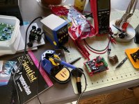
Thanks to all for the recent discussions on adding LED’s to the F5m. I had been thinking it would be nice to have LED’s to verify on/off but am not knowledgable enough to know how to do it so was happy to see brimax’s question and the discussion that followed. I found 22K resistors in my spare parts and followed Ben Mah’s schematic and it worked out very well.
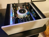
I have been using this amp for a few months now and along with the P3 phono pre it has really raised my level of listening enjoyment. Thanks to all who make these things possible to to an amateur like myself.
The pictures posted in these threads are much appreciated and have been very helpful examples when trying to figure things out.
Here are a few pictures of my build.
Attachments
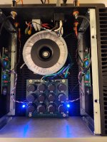

I'm just mocking up the layout for my F5M as bits trickle in, and I have two immediate thoughts;

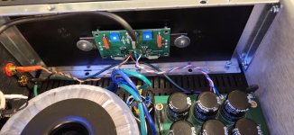
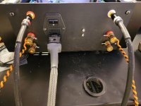
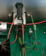
That shield wire off the toroidal is bugging me, also. It's too short to reach the ground post on the bipolar supply for star grounding, so the options are shorten it (as per previous advice in this thread) and attach right near the transformer, or keep the length and get it as close to the ground post as possible. I'm tempted, contrary to my earlier position, to shorten it for the sake of neatness. Next time I order a custom transformer I'll make sure to double the wire length spec.
- Not being able to center the bipolar supply board on my perf base due to the width being a hole short is causing me significant anguish 😂, and
- This PassDIY special edition chassis is huge - even with that 500VA toroidal transformer I feel like I've bought a Dodge Ram to move my carry on luggage.
That shield wire off the toroidal is bugging me, also. It's too short to reach the ground post on the bipolar supply for star grounding, so the options are shorten it (as per previous advice in this thread) and attach right near the transformer, or keep the length and get it as close to the ground post as possible. I'm tempted, contrary to my earlier position, to shorten it for the sake of neatness. Next time I order a custom transformer I'll make sure to double the wire length spec.
I can probably do that. Just an insulated butt splice connector like they sell at Jaycar? Seems straightforward. once lengthened, I can probably route it through the same hole as the AC and connect it to the ground post underneath the perf base. Nice and neat.If that shield wire bothers you just crimp a piece of additional wire, the same colour and attach it to wherever you need it to be.
Once cut it might be difficult to extend it if a need arises.
My 2c.
Shield wire should go to chassis ground at the closest point to the transformer using the shield wire. Rationale: as I understand it, the shield drains off emf to ground so it does not inter couple to the secondary windings of the transformer, and thence to the downstream portions of the power supply. Similarly, if there are high frequency currents induced in the secondary by the power supply (eg diode spikes) and emanations from the actual load circuitry (oscillations, and RF), the shield drains of these to ground so they do not emanate into the power cord and house wiring, which theoretically can act as antennae.
It is my further understanding that many lab instrumentation and medical equipment use shielded transformers. Shields can be incorporated in both toroidal and regular EI laminated transformers. They cost money, so you do not often see them in ordinary consumer electronics. Having the capability to use inter winding shielded toroid transformers at reasonable price is a boon for DIY constructors IMO.
It is my further understanding that many lab instrumentation and medical equipment use shielded transformers. Shields can be incorporated in both toroidal and regular EI laminated transformers. They cost money, so you do not often see them in ordinary consumer electronics. Having the capability to use inter winding shielded toroid transformers at reasonable price is a boon for DIY constructors IMO.
The "keep you alive in the event of a fault" safety ground wire I agree is best on it's own (not shared with anything else) secure spot near the AC inlet, like in this PASS product (one of the preamps I think). Then you can do another star ground on the chassis nearby for whatever else (ground loop breaker, etc.).
Attachments
There are compelling reasons to leave that shield wire short. There are further compelling reasons to NOT use the same attachment point as the safety GND to the chassis. My
Understood. To be clear, I wasn't talking about making it the same connection as the safety ground (we've had that discussion earlier in this thread, I think), I was talking about attaching it under the standoff of the bipolar supply board that grounds it to the chassis, making that the star ground. The word 'standoff' had eluded me last night for some reason (not beer sadly, just fatigue), and 'ground post' came out, which I agree sounds more like I'm talking about the safety ground. So, sorry about that. 😔
Re: reasons for leaving it short, I remember you also expressing that sentiment but I wasn't clear on why that was. Basically I wasn't sure if it was important to performance or more a 'because everyone does it that way'.
Shield wire should go to chassis ground at the closest point to the transformer using the shield wire. Rationale: as I understand it, the shield drains off emf to ground so it does not inter couple to the secondary windings of the transformer, and thence to the downstream portions of the power supply. Similarly, if there are high frequency currents induced in the secondary by the power supply (eg diode spikes) and emanations from the actual load circuitry (oscillations, and RF), the shield drains of these to ground so they do not emanate into the power cord and house wiring, which theoretically can act as antennae.
It is my further understanding that many lab instrumentation and medical equipment use shielded transformers. Shields can be incorporated in both toroidal and regular EI laminated transformers. They cost money, so you do not often see them in ordinary consumer electronics. Having the capability to use inter winding shielded toroid transformers at reasonable price is a boon for DIY constructors IMO.
Aha! That's the bit that I was struggling with. Thank you for that. 🙂
I had the transformer custom wound by local manufacturer TorTech, and they offer if as an option so, not knowing much but assuming it was a good thing, I said 'sure, why not'? 😂
The reason for keeping the shield wire to ground as short as possible is to miminize the possibility that the wire will act as an antenna to re-radiate the shield energy into the interior components/circuits within the chassis, thereby defeating the function of a well designed and constructed chassis/enclosure as a Faraday shield.
The reason for keeping the shield wire to ground as short as possible is to miminize the possibility that the wire will act as an antenna to re-radiate the shield energy into the interior components/circuits within the chassis, thereby defeating the function of a well designed and constructed chassis/enclosure as a Faraday shield.
Right, so, it's like constructing a room to block wifi signals and then putting a wifi repeater inside. I can see how that would be a bad idea. Thanks for that. 🙂
My F5m is sounding great. ( still need to turn up gain since my heat sinks are running at a cool 45c )
I'm now starting to think about building my second one, and having each one as a monoblock. What would need to be done to my current build to modify it to monoblock?
I'm now starting to think about building my second one, and having each one as a monoblock. What would need to be done to my current build to modify it to monoblock?
Do you not have enough power? You can parallel outputs to have 4 per channel or you can run two boards in balanced mode. Running balanced will for sure alter the sound. Paralleling them will alter the sound a bit but not as much. If you parallel the outputs, you will should add gate resistors. The outputs would also need to be matched.
I believe the 140's/9140's being sent to the store are all matched N's and P's. I did not measure them directly but I swapped one F5m Quad for another on a F5m build without altering the pots and both channels measured the same as each other after the swap.
I believe the 140's/9140's being sent to the store are all matched N's and P's. I did not measure them directly but I swapped one F5m Quad for another on a F5m build without altering the pots and both channels measured the same as each other after the swap.
I can't say with any certainty, but I'd lean toward them not being matched in the kits. There's no need for them to be.I believe the 140's/9140's being sent to the store are all matched N's and P's.
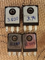
^ Very interesting... None of mine were marked (3 sets). With that said, I got some "early kits". I'll own triple checking and getting a firm answer.
Thanks! 🙂
Thanks! 🙂
I marked them myself after I measured them for my previous reply. They came unmarked. The other quad I had lives in another state inside a F5m...
I suspect that Pass has his ducks in a row in regards to parts. In other words, if he has them, he may as well have them matched as that can be really handy. But one can only speculate. None-the-less, it would be cool if someone else could measure their parts to see.
I just ordered 12x 140 and 12x 9140's for a bridged F5m project that I am wrapping up. I will measure them to see how close they are. I have matched plenty of 240/9240's and they were kind of a broad range.
I test the power Mosfets to .1V within a lot code.
- Home
- Amplifiers
- Pass Labs
- F5m kit