Boricua,I have looked thru the threads and the original articles but have not found the specs. for the output wattage of this amplifier. If someone could mention it, I would appreciate it.
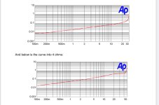
Here is the 📈.
One good first watt, plus some extra for your troubles. 😁
Attachments
20V secondaries would certainly work with the components in the completion kit (includes 35V rated PS caps, etc.). You can multiply the transformer secondary voltage by 1.3333 to get a good idea of where your PS rails will end up, assuming old school bridge rectification like the kit has.My main concern was that it wouldn't work with the supplied components...
-Jose

Is that
my eyes are slightly worse than my ears, so ..... who knows?

Just had to get it going... I used an existing "standard" CRC I had and grabbed a chassis from another project that was being re-worked.. I'll tidy it up a bit. I went toward the upper end of the bias since I had large enough heatsinks.
Sounds marvelous with the Iron Pre.
Thanks to @Nelson Pass!

And some fancy pics... still learning a bit on how to do proper shots.

.jpg")
I didn't install the PSU b/c I already had the other one pretty much ready to go... and I knew I wanted to push the bias a tad higher than the 1A (ish) recommendation from Nelson in the article. I'll likely move it to a more 'petite' chassis in the future and install the provided PSU.
Sounds marvelous with the Iron Pre.
Thanks to @Nelson Pass!
And some fancy pics... still learning a bit on how to do proper shots.
I didn't install the PSU b/c I already had the other one pretty much ready to go... and I knew I wanted to push the bias a tad higher than the 1A (ish) recommendation from Nelson in the article. I'll likely move it to a more 'petite' chassis in the future and install the provided PSU.
Beautifully done!!
Lots of excess heatsink, will be curious to hear your impressions of higher bias.
Lots of excess heatsink, will be curious to hear your impressions of higher bias.
^ Thank you! After seeing yours, I will take some inspiration (steal shamelessly) from your build ideas. I just don't know why I struggle so mightily with wire management. I agonized over mine... and it still looks ...
I know it's all under a top lid and not visible, but I know what it looks like under there.
Someone once said.... neatness counts. Occasionally I listen.

Also... I hope he doesn't mind, but HUGE shout out to @rhthatcher ... using those little softstart / cap boards has changed my life.
Edited to add - When I get back home, I'll do some measurements and try to do some listening from 1A to 1A6 (ish) per channel. I had that "kid at Christmas" vibe going and wanted to get a few hours in before I had to shut it down and head out. It's set at (going from memory) .800V across the source resistor => 1A4 at the moment. Amp things are so subjective and system dependent (as you know), but the original store F5 came out of my system pretty quickly. Then I put it back in once I learned to play with P3 and set it. Then... I loved it. This one had me tapping my toes 'right out of the box'. So... whatever that's worth. Everyone has their own preferences, but for an absolutely 'cute little bugger' like this... it almost has no right to sound as good as it does. Oh yeah... it's a Nelson Pass design.... So... 🙂
I know it's all under a top lid and not visible, but I know what it looks like under there.
Someone once said.... neatness counts. Occasionally I listen.
Also... I hope he doesn't mind, but HUGE shout out to @rhthatcher ... using those little softstart / cap boards has changed my life.
Edited to add - When I get back home, I'll do some measurements and try to do some listening from 1A to 1A6 (ish) per channel. I had that "kid at Christmas" vibe going and wanted to get a few hours in before I had to shut it down and head out. It's set at (going from memory) .800V across the source resistor => 1A4 at the moment. Amp things are so subjective and system dependent (as you know), but the original store F5 came out of my system pretty quickly. Then I put it back in once I learned to play with P3 and set it. Then... I loved it. This one had me tapping my toes 'right out of the box'. So... whatever that's worth. Everyone has their own preferences, but for an absolutely 'cute little bugger' like this... it almost has no right to sound as good as it does. Oh yeah... it's a Nelson Pass design.... So... 🙂
Last edited:
Thank you! After seeing yours, I will take some inspiration (steal shamelessly) from your build ideas. I just don't know why I struggle so mightily with wire management. I agonized over mine... and it still looks ...
Nelson wrote,I have looked thru the threads and the original articles but have not found the specs. for the output wattage of this amplifier. If someone could mention it, I would appreciate it.
The amplifier takes advantage of the square law character of Field Effect Transistors to have
a graceful transition from the Class A region for a wide range of bias levels, even when
presented with high current into lower impedance. Here is the current waveform experienced
by one half of the output stage as it approaches shutoff at 50 watt peak into 8 ohms:
Based on this and the previous graphs, I'm thinking 25 watts of beautiful music into 8 Ohms, easy.

Manolo47 said:
I have looked thru the threads and the original articles but have not found the specs. for the output wattage of this amplifier. If someone could mention it, I would appreciate it.
According to Pass' pdf cut/paste below...
My estimated maximum dissipation of each of the two output devices per channel is about 35 watts, so given my default +/-24V rails, I have calculated the maximum bias for each channel, which range from 1.1 to 1.4 amps.
@ItsAllInMyHead did you felt the need for some multi turn trimpot while adjusting the bias? How smooth was the ajustement with those one turn pot?
My question is how did NP's elves get the Completion Kit packed into that small bag and sealed???
I can't! 🤔
I can't! 🤔
@Ylab - I don't have access to all my silly .gifs at the moment (lucky readers)....
PATIENCE, Danielsan -
It's actually not too bad at all. I don't think multiturn is needed. A few things.
Here's what I did.
Edited to add for (hopeful) clarity - I wasn't trying to get bias dead on AND offset dead on. I was more focused on getting offset closer to 0mV. I don't know why I obsess over offset... it's an illness.
So once the bias was close enough (to me) with the sinks at equilibrium I only tweaked one of the pots to null offset. I think I wound up with 798mV on one channel and 804 on the other with <0.2mV offset on both channels with the lid on and not touching anything for 30 minutes in the rack. If a mouse breaks wind the bias changes... so I don't worry that much about the absolute (within the channel) or relative bias (between channels).
Edited one more time... 🙂 - I forgot to mention (I was up waaaaaaay too early this morning) another big kudos... the post above reminded me. Whoever packed those kits is a hero. Everything arrived flawlessly packed. A little bundle of joy...
PATIENCE, Danielsan -
It's actually not too bad at all. I don't think multiturn is needed. A few things.
- As with the BA-3 FE and a few others.... the bias will drift with temperature. More than you might expect. Mine drops about 50 to 60mV across the source resistor with the lid off. It starts to move almost immediately. Don't breath. (Kidding).
- Set aside about 2 hours if you want to get it 'really dialed in'. But... wiser minds would likely say close enough is good enough.
Here's what I did.
- Made sure pots were full CCW as Nelson recommended.
- Made very small and roughly equal turns on both pots until one of the voltages moved (offset or bias).
- Got close on nulling offset. Here's when you figure out which way makes offset go positive or negative and the relative movements of the pots for moving bias and offset relative to each other.
- Made tiny teeny movements <20mV or so each. Bump up bias and offset increases (as you expect). Null offset with the other pot. Just wee tiny movement almost always CW with each pot unless I bumped it too hard.
- Stopped at ~2/3 of desired bias. Didn't really try to get offset perfect.
- Let it sit for 30 mins (I had bigger sinks to warm up)
- Bias crept up a good bit as expected when sinks / devices got toasty.
- Slid top panel just enough to get to 1 channel. Gave it a little blip ... close to nulled offset. Slid panel. Wash, rinse, repeat. Do other channel.
- Once I had the bias 'close enough', I let it sit for another 30 minutes and made very tiny adjustments. Slide lid... TINY bip on the pot. Wait. The offset was surprisingly (to me) stable at temp deviations. As mentioned, bias is highly temp dependent.
Edited to add for (hopeful) clarity - I wasn't trying to get bias dead on AND offset dead on. I was more focused on getting offset closer to 0mV. I don't know why I obsess over offset... it's an illness.
So once the bias was close enough (to me) with the sinks at equilibrium I only tweaked one of the pots to null offset. I think I wound up with 798mV on one channel and 804 on the other with <0.2mV offset on both channels with the lid on and not touching anything for 30 minutes in the rack. If a mouse breaks wind the bias changes... so I don't worry that much about the absolute (within the channel) or relative bias (between channels).
Edited one more time... 🙂 - I forgot to mention (I was up waaaaaaay too early this morning) another big kudos... the post above reminded me. Whoever packed those kits is a hero. Everything arrived flawlessly packed. A little bundle of joy...
Last edited:
My estimated maximum dissipation of each of the two output devices per channel is about 35 watts,
I think the single turn pots are better than the 25turn in the “classic” F5, as during the dead band the 25 turn require a lot of movement with nothing showing for it, which makes the process seem very arduous and mysterious.
The single turn are touchier, but more immediate, and the bias process is easier because of it.
Also, if you are building F5 of any version, it’s incredibly easier to bias it with 3 meters. When cheap ones work just fine. Use F5 as an excuse to buy some new meters.
😎
The single turn are touchier, but more immediate, and the bias process is easier because of it.
Also, if you are building F5 of any version, it’s incredibly easier to bias it with 3 meters. When cheap ones work just fine. Use F5 as an excuse to buy some new meters.
😎
Went back and refreshed my failing memory and saw where it was 25 watts?
Why 3?3 meters
Zen:
"dissipation"
Meaning heat dissipation?
Not output power?
Is the F5m then rated at 25W as most all of Pass' Amps?
Forgive, brain is still dull from last radiation.
"dissipation"
Meaning heat dissipation?
Not output power?
Is the F5m then rated at 25W as most all of Pass' Amps?
Forgive, brain is still dull from last radiation.
Much easier and less chance of dropping a probe while amp is hot. Dual Mono I use 6. While adjusting you can read the trend on 3 meters better then 1.Why 3?
- Home
- Amplifiers
- Pass Labs
- F5m kit