if the pcb's will also be available without parts?
Well, if you look at both schematics, you can see that leaving out the famous P3 and putting one jumper across it's outer 2 pins will turn any F5 PCB into a F5m. The former you can still get from the DIY store, maybe elsewhere also ?
And of course you can decide what other components to leave out and what not, like all the current limiter etc.
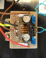
Equally, the circuit is simple enough to do P2P on Vero board.
The topology is the same as our F5 Headamp.
Just larger components with different values. 🤓
https://www.diyaudio.com/community/threads/f5-headamp.271926/post-4277681
Patrick
Attachments
Last edited:
That is good, do you have a link to the gerbers or advise where the post is thanks.Prasi did an F5 layout with gerbers. I have some here and studied them just yesterday and was pretty sure even I could make it into an F5M.! That may help you
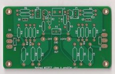
I have seen at least 5 different versions on offer on the inet.
Here is just one of them.
You could study them first before choosing one.
And will likely not cost more than you order yourself with Gerber.
Especially with 70um copper.
But as I said, very easy to do P2P.
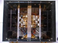
Like all the original Kaneda amplifiers, which are more complex.
Patrick
.
Here is just one of them.
You could study them first before choosing one.
And will likely not cost more than you order yourself with Gerber.
Especially with 70um copper.
But as I said, very easy to do P2P.
Like all the original Kaneda amplifiers, which are more complex.
Patrick
.
Attachments
Last edited:

Not to forget the one from the DIY store.
https://diyaudiostore.com/collections/circuit-boards/products/f-5
Patrick
https://diyaudiostore.com/collections/circuit-boards/products/f-5
Patrick
Attachments
I agree Patrick, the original F5 pcb can be very easily modified to turn it into an F5M, a link or 2 , add R5 and leave out a lot of the original F5 components.
I agree Patrick, the original F5 pcb can be very easily modified to turn it into an F5M,
a link or 2 , add R5 and leave out a lot of the original F5 components.
This is how.
Patrick
.
Attachments
If you want to be exact, change R9 to 15k, and R10 to 33k in the schematics above.
The signal source sees R9 in series with R10, i.e. 48k.
The JFET gates see R9//R10, i.e. 10.3k.
They correspond to 47k and 10k respectively to the schematics in post #1.
It does form a potential divider which attenuates the input signal by 3 dB.
But a 2Vrms at the input will still be able to drive the amp to clipping.
For me no issue.
Patrick
Last edited:
Thanks again Patrick, I will dig out the F5 pcb's I have somewhere.
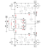
Also in your image in post #70, remove resistors R3 and R4 and change value of pots P1 and P2 to 1K as per the schematic in post #1- then you have the exact circuit NP has come up with.
Also in your image in post #70, remove resistors R3 and R4 and change value of pots P1 and P2 to 1K as per the schematic in post #1- then you have the exact circuit NP has come up with.
Nice!. Thanks, Nelson!
Adding another tab to my spreadsheet of builds to accomplish.

Adding another tab to my spreadsheet of builds to accomplish.
I never used the NTC in the F5X (with 2x dissipation).
Nor did I used the current limiter.
https://www.diyaudio.com/community/threads/f5x-the-euvl-approach.183362/
You just need to know what you are doing.
No need to follow blindly.
Patrick
Nor did I used the current limiter.
https://www.diyaudio.com/community/threads/f5x-the-euvl-approach.183362/
You just need to know what you are doing.
No need to follow blindly.
Patrick
Remove resistors R3 and R4 and change value of pots P1 and P2 to 1K as per the schematic in post #1- then you have the exact circuit NP has come up with.
You obviously missed the point.
Using a 2k resistor in parallel with a 5k pot means only about half of the current goes through the pot.
Pots never have the same specs as a fixed resistor in terms of voltage coefficient, tempco, etc. and hence distortion.
I personally would even use 1.3k // 10k pot.
And then replace the trim pot with fixed resistor after trimming.
No need to follow blindly. 🙂
Patrick
Last edited:
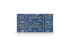
That is the PCB I used for my F5m build discussed here: https://www.diyaudio.com/community/threads/pass-f5m.406472/post-7531709Not to forget the one from the DIY store.
https://diyaudiostore.com/collections/circuit-boards/products/f-5
Patrick
- Home
- Amplifiers
- Pass Labs
- F5m kit