You are correctit appears the one included in the F5M kit are green Vishay wirewound resistors(going off of appearance
Check the BoM provided in the article - Post #1 or...cannot otherwise confirm)
Part listed in BoM In Article

Thank you I forgot the article had a BOM. could’ve saved a bit of money on the part and got the correct tolerance
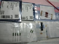
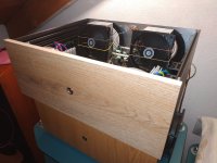
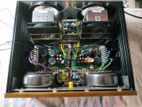
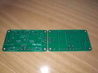
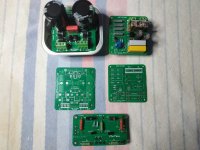
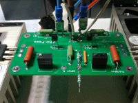
Here is my parts...im waiting the my own pcbs to make another module like Hiraga le Monstre. I will place it in the same AN 39 box as the module Hiraga so that I can listen to it with the same power supply as I did with the Hiraga module . PSU cap multiplier about 22.5-23V /1.5A
Attachments
I am building another F5m, but this time with the dual power supply. I have read thru the build guide but want to know the difference in wiring between single and dual power supply. Also, if there is any changes to be made on the power boards.
I will be using a 3U-400 Modushop Dissipante chassis and two AS-4218 400VA Transformer from Antek.
Thanks
I will be using a 3U-400 Modushop Dissipante chassis and two AS-4218 400VA Transformer from Antek.
Thanks
Two 400VA transformers for a dual mono PSU seems like major overkill. Two 200VA are even more than needed.
You sure that'll all fit in the 3U/400 chassis.
As for wiring, what specifically are you looking to understand?
You'll need a separate fuse for each of the dual PSUs to start off.
You sure that'll all fit in the 3U/400 chassis.
As for wiring, what specifically are you looking to understand?
You'll need a separate fuse for each of the dual PSUs to start off.
Wire each PSU like stereo except only one output board per PSU.
As birdbox mentions, 2x400VA is overkill. 2x200VA is still a bit of overkill but the Antek 100VA wouldn't be enough unless you bias it lower.
As birdbox mentions, 2x400VA is overkill. 2x200VA is still a bit of overkill but the Antek 100VA wouldn't be enough unless you bias it lower.
I have built a F5m with single power supply using a 400VA and like the sound so I didn't want to change anything.
I am using a 3U-300 chassis and did some measurement and the 2 400VA transformers will fit sideway laying down. The 3U-400 chassis will give me the room to fit the 2 power boards side by side behind the power transformers. Would using the 400VA transformers (except for overkill) create any problems with the power supply boards an/or amplifier boards. If it is not advisable, I can order some 200VA transformers.
I just want to know if there is any wiring changes I need to make on the power boards for using them as single power supply. The build guide only provided instructions on using one single power board, so should I follow the same instructions for both power boards and supply the two transformers with separate wires from the power switch going thru 2 fuses.
I noticed that there is a jumper connection on the power board, do I need use this, also can I connect the amplifier board to either side of the power board.
Hi Birdbox,
Thanks for the help again...I guess I have to get a different switch since the one I have only has one fuse built into the switch.
Thanks for all the help.
Yes, you need to use the jumpers if you are using Nelson's PSU as dual mono PSU setup. I showed a picture back in post #2160
You use the same PEM with the one fuse, but the AC line/hot and neutral are split into two outputs and you put another fuse on each of the hot/lines.
I used fuse holders like this on my dual mono PSU for an F4 that mount on back panel for easy access, but there are many options.

You use the same PEM with the one fuse, but the AC line/hot and neutral are split into two outputs and you put another fuse on each of the hot/lines.
I used fuse holders like this on my dual mono PSU for an F4 that mount on back panel for easy access, but there are many options.
Last edited:
Thanks Birdbox,
I think I got it..run two jumpers on each of the power board, then the rest of the connections are the same except only one amp. board is connected to one power board. I guess it doesn't matter which side of the power board the amp. board is connected.
Run 2 cables from the power switch, going thru 2 fuses and connect to the rectifiers, then the connections are the same for both power board as the single power supply set up.
Thanks..
Hi my friends.
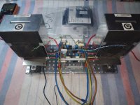
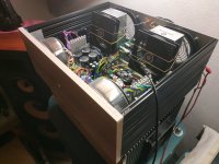
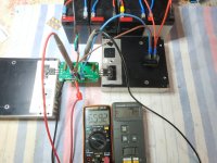
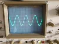
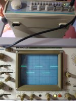
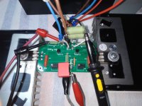
Start up.....after warming about 1.4A bias offset 1-3mv without load.
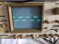
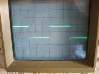
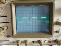
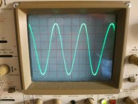
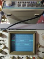
Test sine wave 1-10-20 khz also square wave 1-10-20 with overshooting.
The trimmers on pcb meters 472Ω and 489Ω.
Οn resistors 0.47Ω 670mv and 667mv.
Jfets matched at 8.92 ma idss.
Start up.....after warming about 1.4A bias offset 1-3mv without load.
Test sine wave 1-10-20 khz also square wave 1-10-20 with overshooting.
The trimmers on pcb meters 472Ω and 489Ω.
Οn resistors 0.47Ω 670mv and 667mv.
Jfets matched at 8.92 ma idss.
Attachments
-
 IMG_20250330_122412.jpg340.8 KB · Views: 68
 -
 IMG_20250330_115329.jpg443.8 KB · Views: 68
 -
 IMG_20250330_122514.jpg284.9 KB · Views: 64
 -
 IMG_20250330_122504.jpg303.4 KB · Views: 46
 -
 IMG_20250330_122451.jpg293.9 KB · Views: 47
 -
 IMG_20250330_122434.jpg290 KB · Views: 45
 -
 IMG_20250330_122421.jpg339.7 KB · Views: 55
Last edited:
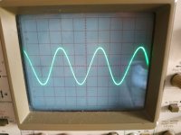
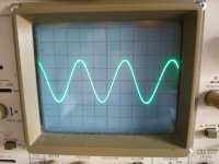
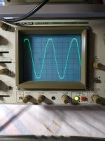
And with load 3.8Ω .... the sine wave before clip ...
any suggestions? for overshooting? Its not for my gen.....
If I remember well in some post, another member had shown the same thing....
any suggestions? for overshooting? Its not for my gen.....
If I remember well in some post, another member had shown the same thing....
Attachments
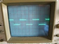
Overshoot on the leading edge of a square wave indicates a high frequency boost:
https://sound-au.com/articles/squarewave.htm
You can investigate further by doing a sine wave frequency sweep with a constant input voltage and monitor the output voltage. It looks like you have a two channel oscilloscope so you can monitor both the input and output signal voltage.
I can't help with the diagnosis but further investigation will get you more information as to the frequency response of the amplifier, which may lead to diagnosis by others who know more than I do. 🤓
Added:
By the way you can see Nelson's measurement of the F5M's frequency response in his pdf article in his post #1. It shows a high frequency roll-off.
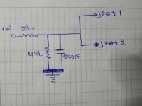
One possible reason for a high frequency boost is oscillation. A possible fix for that is to insert a 100R to 200R resistor in series with the output mosfet gate.
https://sound-au.com/articles/squarewave.htm
You can investigate further by doing a sine wave frequency sweep with a constant input voltage and monitor the output voltage. It looks like you have a two channel oscilloscope so you can monitor both the input and output signal voltage.
I can't help with the diagnosis but further investigation will get you more information as to the frequency response of the amplifier, which may lead to diagnosis by others who know more than I do. 🤓
Added:
By the way you can see Nelson's measurement of the F5M's frequency response in his pdf article in his post #1. It shows a high frequency roll-off.
One possible reason for a high frequency boost is oscillation. A possible fix for that is to insert a 100R to 200R resistor in series with the output mosfet gate.
Last edited:
Ben Mah
Thank you very much for your response.I don't see any oscillation with the poor oscilloscope I have on a sine wave test at 1 -10 -20 - 100 khz .
Also i don't like the 10k resistor.....
I suspect the jfet which have high idss 8.92 ma or the outputs mosfets as well.
I have not seen almost any member who has built the amplifier post results of measurements with an oscilloscope, especially on a square wave signal. If I remember correctly, someone had mentioned overshooting.But I'll have to scroll through the pages to find it.
Maybe Mr Nelson wants to help us.
Last edited:
The sign wave test was for frequency response. Please read my previous post again. Look for increasing voltage output as the frequency increases. If there is a drastic increase at a high frequency that is a sign of oscillation.
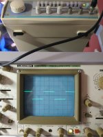
I did the test my friend Ben Mah with constant input voltage with different frequency sweep and i don't saw any changes on voltage output. The overshooting still there....
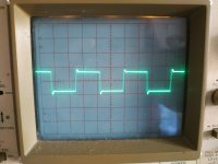
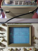
The solution that i found.....
20khz
10khz
40khz
1khz
A perfect Square wave.All these test with load 3.8Ω
The solution that i found.....
20khz
10khz
40khz
1khz
A perfect Square wave.All these test with load 3.8Ω
Attachments
-
 IMG_20250331_175850.jpg349.6 KB · Views: 71
 -
 IMG_20250331_175726.jpg341.1 KB · Views: 67
 -
 IMG_20250331_175712.jpg337.9 KB · Views: 63
 -
 IMG_20250331_175701.jpg334.1 KB · Views: 66
 -
 IMG_20250331_183251.jpg261.6 KB · Views: 80
 -
 IMG_20250331_184925.jpg362.9 KB · Views: 71
 -
 IMG_20250331_185650.jpg490.9 KB · Views: 67
Last edited:
- Home
- Amplifiers
- Pass Labs
- F5m kit