If you had oscillation, I would have expected the other source resistor to be affected by the mishap. How similar were the voltage drops over R12 and R112 after warmup?
Christian: Can you please infer what happens when one junction is uncompensated at the onset of thermal runaway? I am guessing, going by the number of Turbo and similar builds that seem to be suffering from similar issues, that one should ideally compensate both junctions either by using the original scheme of pinching the total gate drive across R1/R2 with a single thermistor, or using a thermistor for each output device.
Thoughts?
Thoughts?
Adding more thermistors will not have a huge impact in my mind. What happens here is something else - the thermistor is not very important in the F5, it is only there to provide some stabilization during warmup.
Fqa19n20 devices are heavily counterfeited. I have encountered them in the "official" chain. It is why I switched to 16n25c. Other than that, I would be looking at Vgs mismatch. If it's off enough, one fet will draw more current and overheat. Sometimes just switching positions in the chain can affect sharing.
Hi,
I'll post additional information later today after work. I deeply appreciate the comments.
I wondered about the FQA19N20s, but I purchased a large number of them years ago from a reputable source (I'd need to look it up) and they are very closely matched (by me). I have been working may way down through them over the last 4 years or so. I also have used them on previous F5 builds without any problems at all. Still, this is wise advice and something I have wondered about.
Christian, I agree completely on wondering why only a single MOSFET and single source resistor(s) would go from theoretical oscillation. But I had hypothesized that, perhaps, all the resistors and MOSFETs could have been hot and oscillating until one N-channel device shorted and immediately discolored that source resistor(s) and blew the fuse. Still, this appeared to be an acute event that happened the second I disconnected the input cable. Yet on the other hand, I lost three MOSFETs on the other board last time, as though there might have been oscillation.
In this build I used closely matched MOSFETs and also matched source resistors (measuring voltage drop for given current flow).
This amp is identical to the last F5 turbo I built (which works fine) using your wonderful boards except that this is a dual mono (two power supplies and transformers) in a different chassis with higher volt rails (40 V versus about 30 V) and with P3 added.
More info later today.
Steve
Increased rails means increased Yfs, which I believe reduces input capacitance, which would increase bandwidth. Perhaps you are right about a small oscillation throughout which triggered one fet to take off.
so , slightly increased gate resistors , with some weeny capacitance across feedback resistors .....
hope that could be enough
hope that could be enough
Nelson showed that bypass cap in the bigger versions, as you say. There has been the suggestion to increase gate resistors to 100r.
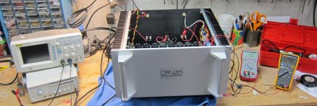
I disconnected power to the left board, installed the repaired right board an powered up the amp with a light bulb – no problems. Then powered up the amp with both boards active. The repaired board biased up fine to 0.8 A and offset < 2 mV. (photo 1)
So I set up for some measurements. Again, no changes have been made other than the repair.
Conditions – R channel:
8 ohm 100 W power resistor load
Signal generator in to R channel through RCA jack
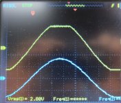
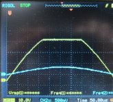
Scope bottom blue trace measuring output of signal generator (input to amp)
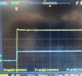
Scope top yellow trace measuring output of amplifier
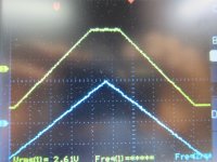
1 KHz sine, triangle, and square waves. Then 3 KHz of the same.
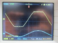
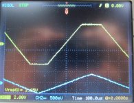
For sine and triangle waves, I increased signal generator output looking for ringing on the amp output, especially near peaks and saw nothing. So then I increased well into clipping and adjusted scope to display individual cycles. I didn’t think I saw anything on the sine or triangle waves and took a couple shots (photo 2 and 3). However, I will say that the horizontal portion of the clipped output wave did wiggle and quiver on the scope, but just barely. It was much more obvious in life than can be appreciated in a photograph. The digital scope, of course, gives us pixels rather than a smooth trace. But any pixel above the horizontal trace in the photo would disappear and then reappear, causing the quivering. This appeared extremely minor and I wasn’t sure if it was just noise. It was most apparent on the triangle wave in the photos.
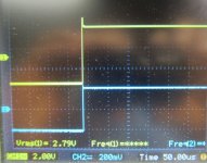
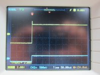
Square wave showed overshoot, but not much else. (photo 4).
3 KHz was same as 1 KHz.
So I set up for some measurements. Again, no changes have been made other than the repair.
Conditions – R channel:
8 ohm 100 W power resistor load
Signal generator in to R channel through RCA jack
Scope bottom blue trace measuring output of signal generator (input to amp)
Scope top yellow trace measuring output of amplifier
1 KHz sine, triangle, and square waves. Then 3 KHz of the same.
For sine and triangle waves, I increased signal generator output looking for ringing on the amp output, especially near peaks and saw nothing. So then I increased well into clipping and adjusted scope to display individual cycles. I didn’t think I saw anything on the sine or triangle waves and took a couple shots (photo 2 and 3). However, I will say that the horizontal portion of the clipped output wave did wiggle and quiver on the scope, but just barely. It was much more obvious in life than can be appreciated in a photograph. The digital scope, of course, gives us pixels rather than a smooth trace. But any pixel above the horizontal trace in the photo would disappear and then reappear, causing the quivering. This appeared extremely minor and I wasn’t sure if it was just noise. It was most apparent on the triangle wave in the photos.
Square wave showed overshoot, but not much else. (photo 4).
3 KHz was same as 1 KHz.
Attachments
L Channel, same conditions:
Photo 1 is the sine wave. A bit more quivering than the other channel, but extremely minor. You can see what I mean by minor ringing on the clipping on the initial negative swing, if this is ringing.
The triangle wave was a bit noisier than the other channel, as well (photo 2).
And the square wave demonstrated overshoot again, and minor quivering during all of the duty cycle.
I repeated this on both channels using 4 ohm loads, and the signal was the same. Again, the same at 3 KHz as well.
Before I go on, I wondered what people think of these tracings. My initial impression was that there was little to no evidence of ringing, but I did notice the quivering and, of course, the overshoots on the square waves.
Attachments
Zen,
Could you expand on your comment?
1. Does overshoot equal ringing in your view, or at least the beginning of it?
2. Are there instances, then, when overshoot that is quite limited turns into ringing at 10 KHz, compared to 1 KHz or 3 KHz?
Thanks
Steve
Could you expand on your comment?
1. Does overshoot equal ringing in your view, or at least the beginning of it?
2. Are there instances, then, when overshoot that is quite limited turns into ringing at 10 KHz, compared to 1 KHz or 3 KHz?
Thanks
Steve
I think you have found your problem, if I am guessing, and it can be dealt with as Zen suggested. You might be surprised by simply changing gate resistors.
I continue my story.
Regardless of being unsure whether the slight quivering I was seeing reflected ringing or noise, I decided to increase stability of the amp, given loss of MOSFETs on two occasions and the overshoot on the square wave. In communications with 6L6 and Bear prior to taking these measurements, they also agreed that they would probably make some changes to increase stability if nothing definite was found on testing. I could add a 1 nF cap between the drain and just before a MOSFET gatestopper as shown on the F5 turbo V3 schematic (and as Zen suggested, Nelson also said that an alternate location was across the feedback resistors). I could increase the gate stoppers on the MOSFETs, and I had brought 220, 340 and 680 ohm resistors 1% tolerance to do that. Or I could do both. Given the overshoot on the square wave and the simplicity, I decided to add a cap on each board. I would run the waves through again and see what this first modification would do before taking further actions.
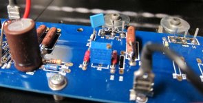
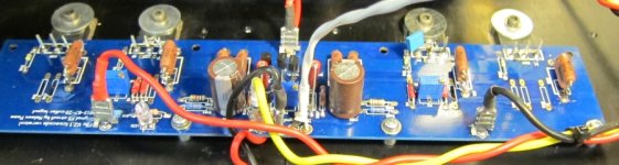
I had with me and used 1 nF film caps. The first photo shows installation between the drain and just proximal to the 47 ohm gatestopper on the same MOSFET. Photo 2 shows an entire board, with the cap on the second MOSFET from the right.
The results of this action were identical on both boards, the same at 4 and 8 ohms, and the same at 1 KHz and at 3 KHz. Photos 3 and 4 show sine and triangle waves during clipping, while photo 5 shows square waves.
All quivering had disappeared. These traces were completely steady. Rock solid. And the overshoot on the square waves was markedly attenuated. In fact, I had not realized how much of the quivering was present prior to the caps until seeing the trace with the caps in place.
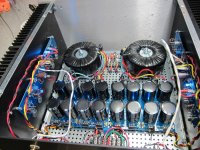
After taking measurements, I also decided to separate the input cable running from the RCA jacks to the boards (shielded twisted pair with shield grounded at one end) from the output runs from the boards to the speaker terminals (photo 6, with new cap circled in red visible on one of the boards), though I doubt this was necessary.
We then hooked the amplifier back up to the theater system. Preamp outputs were from a Paradigm Anthem MRX-700 receiver and speakers were Definitive Technology BP-8060 (front). The amplifier sounded incredible, and we drove it very very hard for a couple days without incident. Very hard. Of course we think it sounds better now, but you always want it to sound better, so who knows? But, I did not disconnect an input cord from the RCA jack while the F5 was powered up again.
If any more MOFETs fail, I’ll increase gatestoppers on the MOSFETs. But hopefully, this will take care of it. On the V3 turbo build 6L6 described, he addressed shorted MOSFETs with both 680R gatestoppers and the 1 nF compensation caps, but found that caps, alone, also took care of the problem.
And if more fail, I’ll be sure to measure voltage drop across each source resistor as well as square waves at 10K. But since I am now a few hundred miles from the amp and the caps are in place, it is a bit late for me to do that now.
And when I build my next V5 turbo with 40 V rails, I’ll use the compensation caps and also probably increase gatestoppers to 220 ohms or so. Maybe Christian can add the optional cap to the next set of boards.🙂.
I appreciate any insights, comments, teaching, and most important, corrections.
Regardless of being unsure whether the slight quivering I was seeing reflected ringing or noise, I decided to increase stability of the amp, given loss of MOSFETs on two occasions and the overshoot on the square wave. In communications with 6L6 and Bear prior to taking these measurements, they also agreed that they would probably make some changes to increase stability if nothing definite was found on testing. I could add a 1 nF cap between the drain and just before a MOSFET gatestopper as shown on the F5 turbo V3 schematic (and as Zen suggested, Nelson also said that an alternate location was across the feedback resistors). I could increase the gate stoppers on the MOSFETs, and I had brought 220, 340 and 680 ohm resistors 1% tolerance to do that. Or I could do both. Given the overshoot on the square wave and the simplicity, I decided to add a cap on each board. I would run the waves through again and see what this first modification would do before taking further actions.
I had with me and used 1 nF film caps. The first photo shows installation between the drain and just proximal to the 47 ohm gatestopper on the same MOSFET. Photo 2 shows an entire board, with the cap on the second MOSFET from the right.
The results of this action were identical on both boards, the same at 4 and 8 ohms, and the same at 1 KHz and at 3 KHz. Photos 3 and 4 show sine and triangle waves during clipping, while photo 5 shows square waves.
All quivering had disappeared. These traces were completely steady. Rock solid. And the overshoot on the square waves was markedly attenuated. In fact, I had not realized how much of the quivering was present prior to the caps until seeing the trace with the caps in place.
After taking measurements, I also decided to separate the input cable running from the RCA jacks to the boards (shielded twisted pair with shield grounded at one end) from the output runs from the boards to the speaker terminals (photo 6, with new cap circled in red visible on one of the boards), though I doubt this was necessary.
We then hooked the amplifier back up to the theater system. Preamp outputs were from a Paradigm Anthem MRX-700 receiver and speakers were Definitive Technology BP-8060 (front). The amplifier sounded incredible, and we drove it very very hard for a couple days without incident. Very hard. Of course we think it sounds better now, but you always want it to sound better, so who knows? But, I did not disconnect an input cord from the RCA jack while the F5 was powered up again.
If any more MOFETs fail, I’ll increase gatestoppers on the MOSFETs. But hopefully, this will take care of it. On the V3 turbo build 6L6 described, he addressed shorted MOSFETs with both 680R gatestoppers and the 1 nF compensation caps, but found that caps, alone, also took care of the problem.
And if more fail, I’ll be sure to measure voltage drop across each source resistor as well as square waves at 10K. But since I am now a few hundred miles from the amp and the caps are in place, it is a bit late for me to do that now.
And when I build my next V5 turbo with 40 V rails, I’ll use the compensation caps and also probably increase gatestoppers to 220 ohms or so. Maybe Christian can add the optional cap to the next set of boards.🙂.
I appreciate any insights, comments, teaching, and most important, corrections.
Attachments

That overshoot looks *very fast*... would be good if that scope had split timebase and you could expand the overshoot - measure the period so know the frequency.
I'd tame it... but it would be nice to know which side it is coming from. I'm guessing it is going to be the side that blew up. So, if you compensated that side, betcha it goes away? Of course for safety, you might want to make both sides the same.
But the same may not be the same numerical values for the compensation components. Might be worth looking at the spec sheets to see the gate capacitance. Usually one complimentary part is different than the other. Depends on by how much...
But, even after that, I'd do some tests as I described in PM, iirc, protect the devices, lower the B+ and try to do the plug in/out and watch for transients... at low enough B+ you will be well within the SOA of the devices so it will be less likely that a full bore parasitic oscillation will smoke the mosfets.
Otherwise, how will you be confident that you can use the amp without being hyper vigilant? And what about an inadvertent interconnect yank out?
_-_-
Edit: you posted as I was pushing the button!
I would compensate it slightly more - get that peak to be as close to flat as possible or just so slightly rounded...
Last edited:
Bear - you and I cross-posted at the same time, and you were not able to see my comment that is now just prior to yours. Caps were added to both boards and it seemed extremely stable after. But if there are more problems that aren't addressed with addition of increased gatestoppers, I'll probably need to drop rail voltage. I went 40 V rails on this build because the user in his theater plays lots of classical music with a wide dynamic range and it is a pretty big room. Without such issues, I would keep it at about 32 V rails, which would also allow for higher bias at the same temp. A very big thanks to you and 6L6 for all the wise advice prior to my investigation and cap installation.
Steve
Steve
Looking at the build, my instinct says to run the power to the board low along the chassis, then UP to the connect points from below. I'd likely run the input as short as possible and rather than out over the filter caps I'd run closer to the board, probably along the top and then to the input point. The speaker run I'd route as far away from the input JFets as I could make it go, and away from the input wires too.
Now the PS and speaker and input wires are no longer parallel and the speaker lines are not near the input circuitry at all.
This might alter the way the square wave looks - but it might not.
It may help the stability.
Another consideration is how the boards "find" PS ground... how that is routed, and how the input ground finds the PS ground too...
_-_-
Next time I go visit, I'll take a variety of small film caps to place in parallel to the 1 nF cap in place at present and do some experimenting. Given the degree of attenuation, I would crudely estimate that another 200 to 300 pF would do the job. However, if that amp works perfectly for the next several months, that probably speaks to the problem being resolved adequately.
For my next build, I'll plan on wire routing using the philosophy you describe, as it would not be any more difficult to build it that way it it certainly would not hurt.
But I need to get some speakers built now.
For my next build, I'll plan on wire routing using the philosophy you describe, as it would not be any more difficult to build it that way it it certainly would not hurt.
But I need to get some speakers built now.
Oops. I see my error. I should have added two caps per board, not one cap. Can't imagine I missed that, but you can see I am striking matches while walking through the dark on this. I needed one cap for N-channel devices and one cap for P-channel devices, though the single cap on N-channel devices appeared to pretty much take care of the issue, and I lost an N-channel device this time and two of them last time. Still this is a mistake on my part that I will need to address. Now I understand your comment, Bear.
Last edited:
Wow Steve, you are not sitting on your hands I must say... 😀
But it is interesting that it works so well just with one capacitor - it seems to suggest that one would need to investigate the CLR loops and find the best possible way to tame it. Any way we can get the frequency - it could easily be close to mhz range...
But it is interesting that it works so well just with one capacitor - it seems to suggest that one would need to investigate the CLR loops and find the best possible way to tame it. Any way we can get the frequency - it could easily be close to mhz range...
- Home
- Amplifiers
- Pass Labs
- F5c (cascode) cviller boards 40 V rails build