Whatever I like😱
I would really like the best of both Pass's, EUVL's and Juma's worlds😀
An EUVL style F5X PCB with Juma's modifications including provisions for 4 parallel K2013/J313 in place of each K1530/J201😎
I know only few are interested in balanced audio gear and I know it is a lot of mosfets (16 of each), but as you might have noted I have plenty of these🙂
I would be happy to share manufacture cost if somebody was to design such a PCB (top quality - of course!). Actually, I would even add a curve traced NNNNNNNNNNNNNNNNPPPPPPPPPPPPPPPP-set of K2013/J313 and a degeneration matched NNNNPPPP-set of K170/J74..............
Of course getting to 25 boards might be a problem🙁
I didn't follow EUVL's F5X thread and also don't want to dig into hundereds of posts. Show me your favoured circuit and I'll see what I can (and are willing) to do... 🙂
I didn't follow EUVL's F5X thread and also don't want to dig into hundereds of posts. Show me your favoured circuit and I'll see what I can (and are willing) to do... 🙂
The official EUVL F5X schematics and BOM can be found in this post. Of course I would be looking for a Juma version of it without current limiting etc. Although I am serious about this you really should not commit yourself if you don't find it interesting. Hakuna matata🙂
oh....and I settled for this special 'F5-version' to scale it down a bit 😀
I'm of course also in for another pair or two of the "original" boards as I guess there may be some fairly simple way of "X-ing" them.
In terms of cost I think electricity is a minor concern😉one thing is certain...electricity is not going to be cheaper
Anyway, I have solar cells on my roof and produce more electricity than I consume🙂
With the two 5r in series with the 200R pot extremes?Personally I would adopt 12r+12r and parallel that with 5r+200VR+5r giving 12r//105r (=10r8 at the midway setting). This avoids setting Rs to zero and avoids setting the Rs of either jFET rather low (which increases the Id and thus heat).
That would give 12r//5r+100r midway (=10R8, as you indicate) and 12r//(5r+0r) (=3R5) and 12r//(5r+200r) (=11R3) at extreme pot position. I think. I guess some nice Susumu 0805 would work nice for this (maybe the same as the 5R1 used on the J74 source).
I don't know if metal film or metal oxide would make any difference to sound quality in the Source lead.
Thin film is metal film and usually avilable in 0.1% & rather expensive.
Thick film is metal oxide and usually available in 1% and relatively cheap.
I would like to use the cheap.
Does anyone have an opinion on sound quality of film vs oxide?
Thin film is metal film and usually avilable in 0.1% & rather expensive.
Thick film is metal oxide and usually available in 1% and relatively cheap.
I would like to use the cheap.
Does anyone have an opinion on sound quality of film vs oxide?
me neither
especially when good wine oxide is in question

Oxidation:
sugar -> ethanol -> aldehyde -> acid
The first two makes me fat and happy😀
The last two gives me a hangover😡
Seriously (if possible), I would really appreciate Nelson's and Zen Mod's opinion on the similarity, difference and complementarity of the "local" JFET degeneration scheme (by EUVL) and the "P3 balance pot" (by Nelson).
What is best? One, the other, or both😕
The first one corrects the imbalance in the open loop.
The last one does it in the feedback loop.
Yes, pick your poison.
And if you are thinking of using 2SK2013 in parallel to replace 2SK1530, I personally would use at least 6x to replace one (for thermal reasons).
And then you'll see there is next to no difference in a number of key parameters any more.
After all, they all come from Toshiba's MOSFET processes at around the same time.
Patrick
> Yes, pick your poison.
I will take a Negroni - a bit complex, but with a magnificent result if done right🙂
> After all, they all come from Toshiba's MOSFET processes at around the same time.
That may be right, but the 1000+ 2013/313 I have traced are still much more linear and complementary than the 1000+ 1530/201 I have looked at. Most of 2013/313 I have were actually fabricated in 2011, so a bit more recent than the 1530/201.
Also, undeniably the 2SK2013 is the FET of the year😀
> The 1000+ 2013/313 I have traced are still much more linear and complementary ...
I do not agree.
We also traced some 1000+ of those, at temperature and the appropriate bias.
But do what pleases you.
Patrick
I do not agree.
We also traced some 1000+ of those, at temperature and the appropriate bias.
But do what pleases you.
Patrick
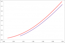
Looks good Patrick - and I do get the point🙂
How did you calculate the 9xK2013 curve?
Obviously making an EUVL F5X "clone" with K2013/J313 would then require 72 pcs. of K2013/J313 fets, therefore costing much more, and all of this with a very doubtful benefit.
I have greatly enjoyed listening to your F5X for a couple of months now and I have learned that I don't need all its power with the speakers I have. Juma's F5 variant (let's call it F5J) with K2013/J313 has had very good reviews, but as the rest of my amplification chain is balanced, it is not really what I'm looking for. Therefore I was thinking about an "EUVL Xed" F5J (F5XJ) with 4 parallel 2013/313 per quadrant.
That should give me an amp with the power of a standard F5, the benefits of balanced operation and the possible better sound of the K2013/J313.
Is this really such a dumb rationale in my situation? I do not pretend it would be significantly better than other existing solutions. I just like experimenting and as I lack specific expertise I was hoping for the advice from the experts in the spirit of this forum.
Cheers,
Nic
...don't need all its power with the speakers I have
since you really want it balanced, how about just 2x 2 pair, balanced, on low voltage
question is, what kind of low voltage would work 😕
Having sufficient power reserve ensures the amplifier work around a small region in the proximity of its bias during normal listening.
This in turn ensures high open-loop linearity and hence low distortion.
Halving the transconductance of the output devices also reduces the open loop gain.
Unless you reduce closed loop gain accordingly, you will change the amount of feedback.
The characteristic of the amplifier WILL change, for the better or the worse.
But try it for yourself.
This is the only way to find out.
Patrick
since you really want it balanced, how about just 2x 2 pair, balanced, on low voltage
question is, what kind of low voltage would work 😕
I was thinking about 15V and 0.5-0.6A bias to run the MOSFETs close to their zero tempo point. An maybe reduce the source resistors on the MOSFETs to 0R1 to get some of the lost open loop gain back. My MOSFETs will be very well matched so I think I can take this risk.
That was what I was hoping to do. I like the learning process, in particular with friendly mentors providing practical advice once in a while 🙂But try it for yourself.
This is the only way to find out.
Patrick
- Status
- Not open for further replies.
- Home
- Amplifiers
- Pass Labs
- F5 with 2SK2013/2SJ313