Thanks, I think I'll attach the regulators to the alu frontplate, it's 10mm thick and 45x18cm large.
If that's not enough I can always add some cooling fins on the frontplate (inside the case).
Not enough...
Last edited:
Yeah, I was afraid so... if I look at the heatsinks of my current F5.Not enough...
How much °C/W does the heatsink needs to be for one regulator (20w) ?
Danny,
You might want to rethink the amount of heat going into that front plate - each Reg is dropping a minimum of 10 volts (4.6V for the Fet, 5+ for Reg margin) so, as Georg says, multiply this by the current and you get a minimum of 12W ea Reg/Rail if amp is biased at 1.2A, and if amp is biased about 1.5A, like mine, then 2 x 15W extra heat per channel (= 30W, or 60W total into that front panel - 80W if using 2A bias, as per above post).
To keep the Fets temp down to maybe a similar 25*C temp rise, will need heatsink about 08*C/W (25*C/30W) for each channel (or 0.4*c/W for the both channels) - in other words, you'll need a dedicated heatsink similar to each amplifiers side heatsinks for the extra Regulators and not just the flat front plate.
However, it seems your heatsinks are huge with 400mm long, 180 high and 10mm fins, if I got that right, so the thermal efficiency might just be good enough to handle this extra 30 watts per channel - Need to check this (the *C/W efficiency of your heatsink)
For example - if your amp is biased to 1.5A, and rails are now +/- 25 volts, dissipation is about 75 watts and if the thermal efficiency of that big heatsink is anywhere near 0.25 *C/W (= temp rise about 18*C), then the extra 30 watts will still only push the heatsiink temp up about another 8*C (= about a 26*C temp rise above room temp) and this is pretty much ideal operating temp, altho appears much higher than the usual operating temp of about 45*C (finger touch test).
Anyway, perhaps this might be useful about your front panel ...
Hi James,
Thanks for the explanation, it's clear now.
I'm thinking of using 4 pairs per channel instead of 3 pairs.
My speakers have a dip to 3ohm in the bass, so 4 pairs should be better.
Biased at 0.4A that gives me 3.2A *22v=70w per channel.
The frontpanel will not do it, it is just 10mm thick without fins.
My case is from hifi2000, the 4U 400*435 model.
Each heatsink has a thermal resistance of 0.23°C/W, more than enough for the output mosfets of each channel.
I think I'll add this heatsink from velleman. Cut it in pieces of 15cm and use 2 pieces back to back for each regulator.
The whole heatsink is 0.19°C/W, so that should do it.
Regards,
Danny
Last edited:
Hi James,
Thanks for the explanation, it's clear now.
I'm thinking of using 4 pairs per channel instead of 3 pairs.
My speakers have a dip to 3ohm in the bass, so 4 pairs should be better.
Biased at 0.4A that gives me 3.2A *22v=70w per channel.
The frontpanel will not do it, it is just 10mm thick without fins.
My case is from hifi2000, the 4U 400*435 model.
Each heatsink has a thermal resistance of 0.23°C/W, more than enough for the output mosfets of each channel.
I think I'll add this heatsink from velleman. Cut it in pieces of 15cm and use 2 pieces back to back for each regulator.
The whole heatsink is 0.19°C/W, so that should do it.
Regards,
Danny
Your configuration will dissipate ~ 100W per channel. So there is no mandatory need for additional heat sinks for the regulators.
Big buggers - at 0.23*C/W, you could just hanh the regulator Fets off the same sink - at 1.6A, and assume 20V rails, thus about 30 from C-R-C gives a power consumption of about 30 x 2 x 1.6 which is near enough to 100 watts that'll create a temp rise of 23*C -
I'd go with that, before going nuts with extra fins and stuff - maybe add some extra cooling vents on bottom and top lids - I usually leave a 10 - 15mm gap each side on the bottom, clear of the heatsinks, for extra cooling breeze and open mesh on the top - the diodes will need a separate heatsink as these need to be kept as cool as possible, unlike the power fets.
On a really hot day, just a small cooling fan will keep the temperature down to reasonable - I try to keep my heatsinks up in the mid 50's as the amp sounds quite a lot smoother & better detail when "quite warm" - not everyone comfortable with amps running this hot but with plenty of internal air flow and sensible thermal layout, not a problem.
regarding where/how best to mount/place the regs, I would also consider wires/connections, etc
without having thougt too much about it, my guess is the best place would be at the bottom,somewhere in the middle
but as said, only 'early thoughts, and by far not conclusive in any way
supply schematic/layout ?
without having thougt too much about it, my guess is the best place would be at the bottom,somewhere in the middle
but as said, only 'early thoughts, and by far not conclusive in any way
supply schematic/layout ?
Thx Georg, James !
Nice that I don't need any additional heatsinks for the regulators 🙂
So I have more place inside for capacitors, CLC, softstart, ... cases tend to be always a little too small on the inside 😉
The HiFi2000 case already has ventilation holes in the top and the bottom, so that's OK.
Each diode will get its own small heatsink, like I did in my "regular" F5 build.
I got the case, enough heatsinks, most parts,... the build can start !
Regards,
Danny
Output protection
I am gathering the parts to build this amp. I plan on using 2 switchers to get the +/- 20V. I'm not interested in getting into the switch vs linear debate. I'll let you know how it sounds😀
But I am concerned about what happens if one of the rails gives way. It is sure to destroy the speakers.
So I was thinking about some very crude speaker protection.
Basically a 48V relay sits between the output of the amp and the speaker. The coil needs to see near 40V to turn on. So if a rail blows, the relay coil de-energizes and disconnects signal to speaker.
Thoughts?
Attachments
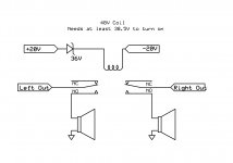
I wire my indicator LED that way.
Across both rails with a Zener + resistor dropper.
The closer the Zener voltage to the rail voltage the more quickly the LED dims as the rail voltage drops.
But A nice idea.
How can it be applied to a "normal" speaker delay relay?
Across both rails with a Zener + resistor dropper.
The closer the Zener voltage to the rail voltage the more quickly the LED dims as the rail voltage drops.
But A nice idea.
How can it be applied to a "normal" speaker delay relay?
How can it be applied to a "normal" speaker delay relay?
Well, I think a capacitor can be added in there to create a slower delayed start. So that could create more of a slower "normal" speaker delay relay.
But that would also slow down the speaker protection in case of rail failure, so it would not suit my particular needs. But I think it can be adapted for different applications.
Also, I should clarify that the zener does set the threshold so that the coil only activates at a certain voltage. But it is also needed to set the deactivation point since most relays activate at 70 or 80% of rated coil voltage, but deactivate, once triggered, at only 10%, which isn't so great for a protection circuit.
I have acquired and traced a fair number of 2SK2013/2SJ313 in the last period😎
I have attached a plot illustrating the distribution of Vgs and Yfs measured @0.5A and it looks fairly good. In general the devices are remarkably linear in the 0.3-0.9A range and I look very much forward to build a F5/F5X with these😀
I have attached a plot illustrating the distribution of Vgs and Yfs measured @0.5A and it looks fairly good. In general the devices are remarkably linear in the 0.3-0.9A range and I look very much forward to build a F5/F5X with these😀
Attachments
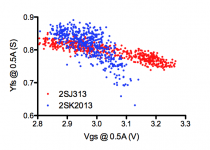
The k2013 seem almost random in comparison to the correlation showing for the j313.
Yfs vs Vgs seems to be strongly correlated for the Pchannel.
Is there a science reason for the Pchannel to show this, or is it just chance that the Nchannel are all over the place?
Yfs vs Vgs seems to be strongly correlated for the Pchannel.
Is there a science reason for the Pchannel to show this, or is it just chance that the Nchannel are all over the place?
Hello,
Being that Georg is out of PCB's, and he's all the way in Germany too, I decided to make a few boards for personal use.
I used ExpressPCB, and the idea is to go econo all the way, meaning no solder mask, silkscreen, etc. So before I order, I figured I'd see if anyone else would like a pair.
For one pair for myself, the cost turns out to be $93 for the pair. If I get 5 pairs made it comes out to be $35 for the pair ($17.50 per channel).
The board has a few slight modifications. First, I am using a spare set of Vicor switching supplies that I have laying around, so I added an inductor on each rail, which can be bypassed if you don't want to use it. Also, I will be using a small fan, so I added a spot for a regulator and connector for the fan. I also added some caps around the feedback resistors and input, but you can totally leave those off.
Board size is 2" X 6.6".
Open to comments if anything seems weird/wrong with layout. Let me know if you want a set. I plan on ordering probably next week.
Thanks
Attachments
I might space the FETs out a little more. Right now they are about 18mm apart, center to center.
Anchan,
I'm be interested in boards for 8 channels, but I would greatly appreciate provisions for the smd degeneration resistor for the J74 JFET. The trick of EUVL used in the F5X. I would also be using Caddock's for the MOSFET source resistors. Maybe you need some transistors🙂
Cheers,
Nic
I'm be interested in boards for 8 channels, but I would greatly appreciate provisions for the smd degeneration resistor for the J74 JFET. The trick of EUVL used in the F5X. I would also be using Caddock's for the MOSFET source resistors. Maybe you need some transistors🙂
Cheers,
Nic
The k2013 seem almost random in comparison to the correlation showing for the j313.
Yfs vs Vgs seems to be strongly correlated for the Pchannel.
Is there a science reason for the Pchannel to show this, or is it just chance that the Nchannel are all over the place?
One of the J313 batches I got my on hands are outliers (high Vgs). Everything under control😉
I my hands they are much more linear and homogenous than the K1530/J201 that I have some experience with🙂
I look very much forward to building a F5X-Juma😀
Anchan,
I'm be interested in boards for 8 channels, but I would greatly appreciate provisions for the smd degeneration resistor for the J74 JFET. The trick of EUVL used in the F5X. I would also be using Caddock's for the MOSFET source resistors. Maybe you need some transistors🙂
Cheers,
Nic
8 channels will certainly bring down the cost, so maybe I can help🙂
I'm not familiar with the smd degeneration resistor for the J74. If you have a value, or better yet a specific part number, maybe I'll throw it in.
As for the Caddock FET source resistors, do you have a specific part #? If I can get them, preferably from Digikey or Mouser, here in the US, maybe I'll use them too.
I do already have the transistors. Got the FETs from member PRAKIT, and jfets from Spencer at FET Audio.
- Status
- Not open for further replies.
- Home
- Amplifiers
- Pass Labs
- F5 with 2SK2013/2SJ313