Elektor reported that for which amp ?
in any case - it's hard to beat ( without resorting to some active solution , of which cap multi is almost best possible ) brute force approach - hefty C bank , without any resistive or inductive series element , along with rectifiers and xformer(s) capable to feed that C bank ....... and last , but not least - hefty bypassing that C bank with solid caps ; motor run ones , in range of 50-70uF , are my fave .
strictly speaking of A class amp as load/governor of TES delivery to your precious speaker
you've confused me, I always thought crc or clc is better than ccc?
don't let anyone to confuse you , as long as you can try and hear by your self .
point is in having a choice .......... and having fun exploring things
😉
speaking of R and C
LC is still the best

point is in having a choice .......... and having fun exploring things
😉
speaking of R and C
LC is still the best
and last , but not least - hefty bypassing that C bank with solid caps ; motor run ones , in range of 50-70uF , are my fave.
Gee, it's like a GD viral epidimic.
Attachments
don't let anyone to confuse you , as long as you can try and hear by your self .
point is in having a choice .......... and having fun exploring things
😉
speaking of R and C
LC is still the best
good point, I need to experiment more, then I can offer more useful advice too😉
I have seen this in the Indian Edition of Elektor which usually comprised of re-prints of original articles much after their publication elsewhere. Hence, issue, month and year won't match.
Elektor published a schematic and article entitled, 100 Watts AF Amplifier. It used dual transistors for the inputs, Sanken outputs, DC servo and used triac based protection circuits. It was based on the Ribbon Speaker Amplifier using MAT02, 03 published earlier by Elektor. If anyone can see that article, under PSU, Elektor's comments can be seen.
Similarly, this was repeated in the 60 Watt HEXFET Amp article.
One of these had CRC and the other had RCRC, but I forget which amp had what.
if written in Mag ...... it must be best !
question everything ... especially SS amp articles from Elektor

question everything ... especially SS amp articles from Elektor
F5 with K2013/J313 as Line/Headphone Amp
Finally, I finished this version of amp as describe in post #42 last weekend. I am listening to it as an lineamp for a few days now.
Beside the thermistors that I chose not to use, everything else are as in the diagram in post#42. The sink is big enough for more current but I can only bias it up to 120mA and the regulator's pass trans become quite hot.
I can easily hear big improvement over the original version. Both hi and lo seem more extended. It sounds more opened. I am very very happy with it. Thank you very much, Juma.
I found the jfets are run at about 8mA. I measure about 2V at the source of the jFets. Is this an optimum point?
Attachments
...
I found the jfets are run at about 8mA. I measure about 2V at the source of the jFets. Is this an optimum point?
I'm glad you like this preamp


About that voltage - measured directly at the JFETs Source there should be about 100mV (relative to GND).
Those 2V you measured is probably on the other end of R4 or R5 (further from JFETs Source).
I'm glad you like this preamp
About that voltage - measured directly at the JFETs Source there should be about 100mV (relative to GND).
Those 2V you measured is probably on the other end of R4 or R5 (further from JFETs Source).
😱 You're right. The 2V is on the far ends of R4/R5 from the jFets' source.
It seems to me the jfets are ran at the point near their Idss. Would it be better if we select jFets with higher Idss, say 10 mA, for this circuit?
The most linear region for these JFETs is near the Idss. I usually use them at 70-90% of Idss. That should not worry you - if you are afraid that your JFETs dissipate too much power, you can easily decrease the power supply voltage to +/-15V.
Using higher Idss JFETs won't bring improvement in this case.
Using higher Idss JFETs won't bring improvement in this case.
Only get this so far 🙁
Still waiting for J313/K2013 and heatsink of course 🙂
ps
Can this Amp drive Electrostatic Headphone ?
Still waiting for J313/K2013 and heatsink of course 🙂
An externally hosted image should be here but it was not working when we last tested it.
ps
Can this Amp drive Electrostatic Headphone ?
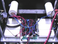
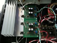
Well after some "trouble", finally finished this up
here some picture
Result
This amp just give me a BIG SMILE
Thank's Juma for replying my PM many times 🙂
here some picture
An externally hosted image should be here but it was not working when we last tested it.
An externally hosted image should be here but it was not working when we last tested it.
An externally hosted image should be here but it was not working when we last tested it.
An externally hosted image should be here but it was not working when we last tested it.
An externally hosted image should be here but it was not working when we last tested it.
An externally hosted image should be here but it was not working when we last tested it.
Result
This amp just give me a BIG SMILE
Thank's Juma for replying my PM many times 🙂
Looks nice and neat, cheap (a lot of small ones are cheaper than one big one ....and a more flexible layout possibilities! ), FC ( i might be wrong but those look like panasonic FCs ) don't come in BIG packages.....😀 would be my reasoning.
Last edited:
Okay. I thought there might some kind of sonic improvement using lots of smaller caps instead of few larger ones.
> Looks nice and neat, cheap, FC don't come in BIG packages..... would be my reasoning.
You forgot one very important one -- much higher total ripple current.
Suggest you also read how the slit foil caps work.
Patrick
You forgot one very important one -- much higher total ripple current.
Suggest you also read how the slit foil caps work.
Patrick
- Status
- Not open for further replies.
- Home
- Amplifiers
- Pass Labs
- F5 with 2SK2013/2SJ313