read the balanced/bridged rule again.
Read what you wrote.
BTW,
your 50w peak?? is into what impedance?
I'll guess you used P= Ipk^2 * Rload / 2 to get that. But forgot the / by 2 factor.
Ibias = 3.6Adc
Imax ClassA ~<7.2Apk
P ClassA = 7.1^2 ^ 2 / 2 = 50W into 2r0.
Double (for balanced/bridged) that to get the maximum ClassA into 4r0, i.e. 50W of ClassA into 4r0 from the balanced amplifier.
I do not know what 2.5 means in Jacco's post. Does anyone else besides Jacco?
Last edited:
I do not know what 2.5 means in Jacco's post. Does anyone else besides Jacco?
🙂
I am shooting for 50W into 4 ohms per post #315.
Your math is just not making sense to me Andrew. You stated that you want to shoot for 25W into 2r0 per half of a bridged/balanced amp so:
Ibias = 2.5A
Imax Class A ~< 5 Apk
P ClassA = 5.0^2 x 2/2 = 25W into 2r0 (for one side of the balanced amp)
Doubling that gives you 50W Class A into 4r0 for a balanced/bridged amp (double the power into double the impedance). I think an Ibias = 2.5A is the "2.5" Jacco was referring to.
Last edited:
For those folks who might have been following earlier discourse about effects of diode in parallel with Rs, should look at internal diagrams Mosfet that come on many datasheets. Picturing internal diagram with diode on source leg gives a nice visual picture of Jacco's comments. Just for the noobs, of course.
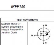
Probably wrong, of course, but i was taking about that diagram with the addition of an external diode representing added diode in F5. Is this not what Jacco was trying to illustrate.
Nevermind. I am officially banning myself from posting on anything other than my own projects. Doing a disservice to anyone trying to learn😀. Thinking about it more, still don't understand. not completely that is.

Nevermind. I am officially banning myself from posting on anything other than my own projects. Doing a disservice to anyone trying to learn😀. Thinking about it more, still don't understand. not completely that is.
You are officialy dis-banned from posting
As promoting discussion is certanly big service to all.
Plus I commend your open attitude in admiting mistakes.


this is correct.I am shooting for 50W into 4 ohms per post #315.
Your math is just not making sense to me Andrew. You stated that you want to shoot for 25W into 2r0 per half of a bridged/balanced amp so:
Ibias = 2.5A
Imax Class A ~< 5 Apk
P ClassA = 5.0^2 x 2/2 = 25W into 2r0 (for one side of the balanced amp)
Doubling that gives you 50W Class A into 4r0 for a balanced/bridged amp (double the power into double the impedance). I think an Ibias = 2.5A is the "2.5" Jacco was referring to.
My 3.6A for bias is wrong. Sorry, I must have rushed the calculation.
rushed
How un-you, remind me again, which was dance night and which one was tossing two lagers for the price of one up yonder loch ?
Please forgive the questions of a neophyte who still has to look up the names for each characteristic to discuss...and is usually too lazy to do so...
Turbo schematics show a pair of diodes in parallel at every instance. So is two of these particular diodes optimized to minimize some kind of "leakage" in one direction or the other while sharing current and heat dissiaption, or is 3 or 4 in parallel even better (to eventually share the current but maybe react more smoothly stepped like an avalanche diode while running cooler)?
Turbo schematics show a pair of diodes in parallel at every instance. So is two of these particular diodes optimized to minimize some kind of "leakage" in one direction or the other while sharing current and heat dissiaption, or is 3 or 4 in parallel even better (to eventually share the current but maybe react more smoothly stepped like an avalanche diode while running cooler)?
Last edited:
- Status
- Not open for further replies.
- Home
- Amplifiers
- Pass Labs
- F5 Turbo is posted