Ok, so I can build the F5 Turbo V2 on the Cviller F5c boards, right ? Anybody got a spreadsheet that translates the Pass component types and numbers to the labels on the boards (ie., Pass C1 = Cviller C3) ? Ok, call me lazy !!
Also, I've got two of Russell Boss's big *** heat sinks, (10.25 x 15 x 24 2.5" fins), one per channel. Anybody know how much these babies can dissipate and stay below 55 deg C ?
Also, I've got two of Russell Boss's big *** heat sinks, (10.25 x 15 x 24 2.5" fins), one per channel. Anybody know how much these babies can dissipate and stay below 55 deg C ?
print them schematic's out and do it your self,I don't think anything like that has been documented,lol....LAZY BOY,lol.
I used pass values first then change if you need to ,but get it going first!
R 101 to 104 4,7k R 5,6,7,8 = 100 R 3w
NS
I used pass values first then change if you need to ,but get it going first!
R 101 to 104 4,7k R 5,6,7,8 = 100 R 3w
NS
Last edited:
looking at spreadsheet, sooo many columns
Would someone be so kind as to break down what each board does? I get that V3 is a beefed up V2 with diodes?
I'm confused on the difference between v2/v3 input boards and the v2 combo board.
I'd like to triamp my speakers and want the F5T for the woofer and mid.
I was going to go balanced input and SE output since pre is balanced and this amp will be in the speaker cabinet. But not sure, maybe all balanced is better?
(Probably going to go with a regular F5 for the tweeter "only 20W ribbon")
Sincerely,
Eternalight
Last edited:
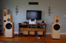
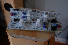
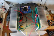
Here are some pics. My system driven by DCB1 into B4ish Xover and on into the dual F5t's. Also some pics of F5t noards with kit components as well as his proto boards. proto boards show diodes mounted both ways, on and off the sink. THis single pair unit was able to drive the 12" woofers you see to high excursion without the fee standing diodes getting warm. Heat is not an issue, but consistency of temps may be. dunno. Hope to listen to nicer boards tomorrow. Getting fet kits out has me busy with little time for listening or playing.
Attachments
Hi Buzz,
Looks like fun ! I like the plywood ,I use it too!
Keep up the good work!
Cheers,
NS
Looks like fun ! I like the plywood ,I use it too!
Keep up the good work!
Cheers,
NS
Hey Buzz, talk to me about those horn speakers you have, what are they? Very interesting. How do they sound? Backloaded horn of some sort.
Double mouth horn by Scottmoose on the forum. I really liked them, but would want a different main driver. What you see is the EL70 version. I even added the second side firing driver. Just didn't like The EL 70 when compared to my favorite A7.3
If it is not too late, please consider me for the group buy of 4 FQA Quad of matched N and P Mosfets (total 32 transistors) and 16 MUR3020 Vishay diode sets.
Greetings to all from a very hot Athens Greece.
Greetings to all from a very hot Athens Greece.
I am totally confused with this thread. My intent was to build a pair of monster V3 monoblocks.
What happened to UK toecutter's modular boards?
Are they or will they be the DIYaudio stores boards?
Where did Tea Bag's boards come from and where are their schematics/capabilities outlined?
Sorry if I've missed these explanations. But it's really confusing.
What happened to UK toecutter's modular boards?
Are they or will they be the DIYaudio stores boards?
Where did Tea Bag's boards come from and where are their schematics/capabilities outlined?
Sorry if I've missed these explanations. But it's really confusing.
Big E,
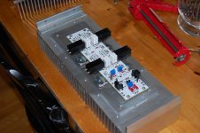
You can see TeaBags baords in the picture. They have the mosfets spaced at the Store's universal mounting distance of 40cm. They have the diodes mounted in between the fets at same spacing. If all are devices are mounted on a sink, then you have a device every 20cm. I have chosen to mount the diodes off board, as heat has not been an issue. My final plan is to have a copper bar connecting them all before being attached to their individual heatsinks to act as a spreader and also for thermal tracking. I am not sure if you can mount all 8 fets on a single sink, run at 1a bias, and get away with it without a fan. Best chance would be to mount them on a heat spreader attaching two sinks together like mine. Ill try to post idea for dual mono later on.
Here is link to his thread.
http://www.diyaudio.com/forums/group-buys/211776-gb-f5t-convertible-amplifier-boards.html
Thanks! I'd appreciate the monoblock info. I've got a couple hundred bucks worth of fets coming, and wanted to used them as monoblocks.
Just now completing the thought process on the Hotrodded DCB1 buffer. A heat-spreader like yours (or copper) will be a must on that project, since the transistors don't reach the heatsinks.
Just now completing the thought process on the Hotrodded DCB1 buffer. A heat-spreader like yours (or copper) will be a must on that project, since the transistors don't reach the heatsinks.
No worries. If i have to, ill design some boards for folks wanting monoblocks. I have adcb1 being used in FE of xover with bias set high with 22ohm resistors and fets floating, and they are ok. Heatsink need is based on bias. You may not even need them.
Big E,
You can see TeaBags baords in the picture. They have the mosfets spaced at the Store's universal mounting distance of 40cm. They have the diodes mounted in between the fets at same spacing. If all are devices are mounted on a sink, then you have a device every 20cm. I have chosen to mount the diodes off board, as heat has not been an issue. My final plan is to have a copper bar connecting them all before being attached to their individual heatsinks to act as a spreader and also for thermal tracking. I am not sure if you can mount all 8 fets on a single sink, run at 1a bias, and get away with it without a fan. Best chance would be to mount them on a heat spreader attaching two sinks together like mine. Ill try to post idea for dual mono later on.
Here is link to his thread.
http://www.diyaudio.com/forums/group-buys/211776-gb-f5t-convertible-amplifier-boards.html
regarding the diodes. i think its a little stupid way to go with fet, diode, fet, diode. you will not get any symetry on dual sinks.
a better way will be fet, diode, diode, fet🙂
Any updates ...?
+1. i'm just about to cut my output boards in two if the new boards don't come soon😀
- Status
- Not open for further replies.
- Home
- Amplifiers
- Pass Labs
- F5 Turbo Circuit Boards