20 x12 heatsink is not enuff...... 😕
Sorry, somehow the attachment got lost. Try again
I agree, unless you use a fan.
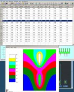
Here is a simulation using a single HeatsinkUSA E007 12 inches long with an air velocity of .679 m/s. The table show results with other air velocities.
Attachments
Anyone know if I can build 7 channels inside of one chassis for my home theater?
Yes, it's possible.
The heatsinks required would be jaw-droppingly large, even with a lot of forced air. Perhaps this would be a good application of wasted-water cooling, but your water bill would be immense.
The PSU would also be a challenge, but not insurmountable. Sourcing a big-enough transformer or two would be interesting.
I realize I'm likely missing something, but I'm not sure why people are planning on trying to fit these amps into a single strangely large and unwieldy case rather than doing monoblock amps as many did with the Alephs running at similar wattages to F5T? Monoblocks allow you to simply have 2 more reasonably sized cases without having to worry about things like 20"-long heatsinks, where to buy them, how to combine them to get the size, how to assemble them in a case that isn't an eyesore, etc. Oh, and monoblocks have that 'serious business' look to them.
I guess I had wrongly assumed that monoblock cases would be typical for most F5T builds.
Austin
I guess I had wrongly assumed that monoblock cases would be typical for most F5T builds.
Austin
I realize I'm likely missing something, but I'm not sure why people are planning on trying to fit these amps into a single strangely large and unwieldy case rather than doing monoblock amps as many did with the Alephs running at similar wattages to F5T? Monoblocks allow you to simply have 2 more reasonably sized cases without having to worry about things like 20"-long heatsinks, where to buy them, how to combine them to get the size, how to assemble them in a case that isn't an eyesore, etc. Oh, and monoblocks have that 'serious business' look to them.
I guess I had wrongly assumed that monoblock cases would be typical for most F5T builds.
Austin
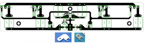
Plus you can split the N and P channel devices so that they are on separate heatsinks. This is exactly what I'm doing and is also why I'm doing my own PCB layout. That being said, I do appreciate the effort UKToecutter has been putting into this!
The heatsink concerns are making me nervous. Plus no help with matching devices from TECH DIY...
But I have a nice collection of PCB's for other amps so:
I'll take 4 amp and 2 PSU. 😀
But I have a nice collection of PCB's for other amps so:
I'll take 4 amp and 2 PSU. 😀
Also, It would be good if somebody could sanity check the BOM's for me.
Q7 and Q8 are reversed on the BOM.
Also, the Mouser part reference for R25 (10k) brings up a 10k7 part that is not stocked. The do have this part in 10k.
Yeah, I definitely think it's great that UKToecutter and the others quickly got on this to come up with a working board! I just wondered what the arguments were in favor of a single big case vs monoblocks given the heat dissipation.
For the thermal simulations, is the mosfet placement considered here? If we could find the optimal placement on the heat sink that is chosen, then the PCB layout should reflect that.
Ungie has an idea. My aleph2 has large sinks with only 3 mosfets per sink. Splitting the board, or at least providing that option would be a plus.
There is no doubt in my mind that this is going to be the biggest consistent problem with this project. The heat rejection requirements are immense!
Still, where the is a will, there's a way, and I'm looking forward to seeing everybody's solutions.
One word answer: cyrogenics.........!
Liquid nitrogen in a dewar jar!
Blimey,
Massive cases!!!
Have you considered forced air cooling?
You might want to check out my old F5 build thread.
1. "Stock" Pass F5 design, standard bias levels
2. Conrad heatsinks
3. Two 120VAC fans, running at 65VAC for reduced speed and noise.
4. Airflow enters the chassis from the rear, flows through the open chassis plenum (cools the toroid, rectifiers, resistors), then UNDER the lower lip of the heatsink base, then UPWARD between the heatsink fins.
5. Airflow exits at top of amp
Outcome: heatsinks are cool to the touch..... (probably too cool). Works well.
http://www.diyaudio.com/forums/pass...usic-different-drummer.html?highlight=drummer
I realize I'm likely missing something, but I'm not sure why people are planning on trying to fit these amps into a single strangely large and unwieldy case rather than doing monoblock amps as many did with the Alephs running at similar wattages to F5T? Monoblocks allow you to simply have 2 more reasonably sized cases without having to worry about things like 20"-long heatsinks, where to buy them, how to combine them to get the size, how to assemble them in a case that isn't an eyesore, etc. Oh, and monoblocks have that 'serious business' look to them.
I guess I had wrongly assumed that monoblock cases would be typical for most F5T builds.
Austin
Maybe the same reason why people change their camshafts .... 😉
I prefer dual monos in one chassis makes for better packaging and less dollars on chassis more for parts .
Maybe the reason cigarette boats have dual engines. Hard to fit 1000 HP in one engine without performance issues.
When I read "put me in for" this or that. I'm wondering if they've read the manual since they usually want half as many power supply boards as amp boards. With V3 you need a power board for each channel.
When I read "put me in for" this or that. I'm wondering if they've read the manual since they usually want half as many power supply boards as amp boards. With V3 you need a power board for each channel.
A v2 only needs 1 PSU in stereo chassis. I should probably see how involved it will be to use this PCB for the V2 with the empty bits.
Finished drawn a F5 turbo V1 in single layer pcb. 😛 Can start playing the F5 turbo soon, hoping everything goes well! 🙂
Very clean layout 🙂 But it would improve even more when turning Q1 & Q2 flat side against flat side, to be thermally tied together. Would provide temp equilibrium that can be a good thing for offset stability, etc.
Best,
nAr
Finished drawn a F5 turbo V1 in single layer pcb. 😛 Can start playing the F5 turbo soon, hoping everything goes well! 🙂
Way to go
why not ad cascode (just a jumper to by pass) and make speaker out track
thicker.
Turbo ready (missing diodes and P3) F5
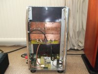
The single box was a pain to lift (especialy as I work in the loft) even with few years experience as Rodie I needed a block to get it up and down
So I have split the build in 3
Main suply box with 1000 VA traffo and the first CRC and 2 separate amplifiers with same more caps
Sinks for the F5 are 12 W 16 H 3 D
Attachments
@UKToecutter:
Maybe it would be the best to make a list of all the guys who would like to have PCB's? 🙂
cheers,
matthias
Maybe it would be the best to make a list of all the guys who would like to have PCB's? 🙂
cheers,
matthias
Q7 and Q8 are reversed on the BOM.
Also, the Mouser part reference for R25 (10k) brings up a 10k7 part that is not stocked. The do have this part in 10k.
Ungie,
Thank you. Changes have been made.
- Status
- Not open for further replies.
- Home
- Amplifiers
- Pass Labs
- F5 Turbo Circuit Boards