I think it's a great idea to have input and output boards which can be used for either V2 or V3
Hey there,
I've cojitated over the board lay-out since the V3 1x front and 2x output drawings were posted......
V1 is basicly F5c from the store - wanna build one, buy boards from store, build amp, jack-up surply V and have sweet music and a slightly warmer listening room.
V2 is F5c with the extra doo-daa's - not much more requirement in the heat sinking/case enlargement side of things, more heat = better heating/drive ability.......
OR V2 with split input-output/s - makes it possible to upgrade to.........
V3...... definately an input board and split out-put device boards. In my head, V3 should be built as mono blocks, 50v or there about surply V and 3 or 4 devices is gonna need heat sinking that will impress any one, crank up to 75v surply V and we're in the realms of massiveness.......
And as Mr.Pass himself said 'DIY'ers are a fearless bunch'
Nice work on the board desighn Toecutter, I've saved the V3 layout just in case this arrangement does'nt go ahead - BUT if it does, I'd be interested in a stereo set of input/split outs
Sorry dudes no way I want to be spoil sport I would like to be really diplomatic
The supply board is a bit to complicated
I think toecutter is doing pretty good job but there are many ways to pluck a Duck.
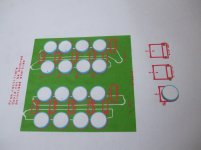
I posted the lay out for how IMO capacitors board could be made simpler with less track lengths and such all is needed is the bit for the rectifiers (again I do not intend to but in see above)
Track thickness can be really large and different size capacitors just need extra pad on the Ground plane.
Low impedance and current caring capacity is really important here
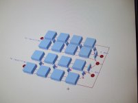
To make it easy to see here is a couple of 3D views with copper poor areas and basic track
Another thing and reason why I did not put rectifiers there
I know Papa published the one with common secondary while F5 had split down to rectifiers and that normally (2 diode Bridges) is the preferred versions.
Do you want one as Turbo PSU or 2 As F5 PSU?
The supply board is a bit to complicated
I think toecutter is doing pretty good job but there are many ways to pluck a Duck.
I posted the lay out for how IMO capacitors board could be made simpler with less track lengths and such all is needed is the bit for the rectifiers (again I do not intend to but in see above)
Track thickness can be really large and different size capacitors just need extra pad on the Ground plane.
Low impedance and current caring capacity is really important here
To make it easy to see here is a couple of 3D views with copper poor areas and basic track
Another thing and reason why I did not put rectifiers there
I know Papa published the one with common secondary while F5 had split down to rectifiers and that normally (2 diode Bridges) is the preferred versions.
Do you want one as Turbo PSU or 2 As F5 PSU?
Attachments
Would just require solder pads, not holes.
That is what I meant, my technical english needs improvement 🙂
Sorry dudes no way I want to be spoil sport I would like to be really diplomatic
The supply board is a bit to complicated
I think toecutter is doing pretty good job but there are many ways to pluck a Duck.
I posted the lay out for how IMO capacitors board could be made simpler with less track lengths and such all is needed is the bit for the rectifiers (again I do not intend to but in see above)
Track thickness can be really large and different size capacitors just need extra pad on the Ground plane.
Low impedance and current caring capacity is really important here
To make it easy to see here is a couple of 3D views with copper poor areas and basic track
Another thing and reason why I did not put rectifiers there
I know Papa published the one with common secondary while F5 had split down to rectifiers and that normally (2 diode Bridges) is the preferred versions.
Do you want one as Turbo PSU or 2 As F5 PSU?
I agree that trace thickness is important. Especially in the power supply board. More is better. I don't think it costs extra to leave more copper on the board. A universal board is good. Maybe the rectifiers could be off the board to cut down on size.
Here is the data sheet:
Fukushima Ceramic Plate Resistors MPC74
The GB was for the straight type MPC74, which looks to have a lead spacing of 9mm with 0.8mm leads.
I have been using those on MY F5 sound realy good no inductive by design
handle a lot of power probably the best for this application.
If things get out of hand they breack quite well (open circuit) which is quite handy if one of the mosfets pop as 99% of the time that is a dead shorth.
I agree that trace thickness is important. Especially in the power supply board. More is better. I don't think it costs extra to leave more copper on the board. A universal board is good. Maybe the rectifiers could be off the board to cut down on size.
Ok that is one comment
What obout the track rooting (again no ego involved here) would you think that 1 single straight track is beter than loads of track with loads of bends
Don't get me wrong bend and duble layers make it look pretty but I think we are not going to put one of those at the Biennale.
Cost wise one get charged by board size and number of holes.
It is actualy cheaper to leve as much cooper on the board as Acid get changed less often but you will get no discount for that.
I would think that bends and corners aren't critical with heavy traces in a power supply, but I don't know for sure.
Probably more important where interference and oscillation can cause problems.
Probably more important where interference and oscillation can cause problems.
Ok that is 2 comments and 49 view of the silly picture in less than 2 hours
camon dudes is your F5 in which ever flawor we working on.
camon dudes is your F5 in which ever flawor we working on.
Ok that is 2 comments and 49 view of the silly picture in less than 2 hours
camon dudes is your F5 in which ever flawor we working on.
Ok Bksabath here is my comment:
1 - Uktoecutter's PSU PCb includes discreet rectifiers and monitoring leds...your's does not.
2- that being said, the simpler the better is my PSU layout moto.
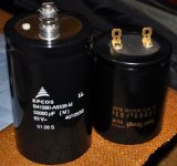
3- Uktoecutter assumes that we will all use small caps ( like Papa has truckloads off ) ..I for one will not for the simple reasons that i don't have tons of them and this board takes up a lot of horizontal space , a PCB like PA's posted earlier by Jacco is better in my opinion, uses fewer and bigger caps.
4 - I know these bigger caps are more expensive and capacitor plate surface area is smaller than a lot of small caps....but engineering is tradeoffs....
So in summing up i would love a more compact PSU for bigger caps and without the rectifiers....these being left out of pcb, can be put is other small spaces available in the case, somewhere near Trafo(s)...more flexible...also more wire i know.....
...my 2 cents worth😀😀
Last edited:
1 Course it does not question is stick with Papa 1 set of diodes or stick 2 set of diodes
Separate trafo taps
What is size of cap you are dreaming about The one of board are 6 mm pitch tiny litle ones still 63 V 10mU
The board lenght is 170 mm and 100 wide.
Monitoring leds that is a constructive comment Bravo
Separate trafo taps
What is size of cap you are dreaming about The one of board are 6 mm pitch tiny litle ones still 63 V 10mU
The board lenght is 170 mm and 100 wide.
Monitoring leds that is a constructive comment Bravo
Last edited:
1 Course it does not question is stick with Papa 1 set of diodes or stick 2 set of diodes
Separate trafo taps
What is size of cap you are dreaming about The one of board are 6 mm pitch tiny litle ones still 63 V 10mU
The board lenght is 170 mm and 100 wide.
Monitoring leds that is a constructive comment Bravo
seems you did not like my comment, it was very much in favour of your approach....
I just limited myself to identifying differences!!!
no judgement of choices, each to his own ...but i would like fewer and bigger caps for a more compact PSU that is all.
I have a few of these caps ...enough for V2 which is what i am aiming for....
Attachments
Last edited:
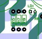
Don't want to put a damper on an exciting project, but I can't help but feel the via (via R15) on the PSU board is a weak link, it wouldn't be too difficult to get rid of with a little re-routing.
That is just for monitoting led...not a problem.
Would you all like an alternative PSU?
I've no problem with that and I don't take it personal.
The PSU board is true to Nelson's schematic but I know alot of you plan to do your own whether they be CRC CC CLC is a matter of personal preference.
If there is a consensus I'm happy to accomodate.
I've no problem with that and I don't take it personal.
The PSU board is true to Nelson's schematic but I know alot of you plan to do your own whether they be CRC CC CLC is a matter of personal preference.
If there is a consensus I'm happy to accomodate.
Don't want to put a damper on an exciting project, but I can't help but feel the via (via R15) on the PSU board is a weak link, it wouldn't be too difficult to get rid of with a little re-routing.
Itsmee
If you look close, there is a track on the underside which is 5mm thick.
Itsmee
If you look close, there is a track on the underside which is 5mm thick.
Exactly, the R15 via is carrying all the current from R1-7 to C10
Hmm, I would hope that wouldn't be a problem, especially when you consider that some power resistors have leads of 0.9mm diameter (e.g Futaba 10W)
- Status
- Not open for further replies.
- Home
- Amplifiers
- Pass Labs
- F5 Turbo Circuit Boards