I've searched but have not found a helpful guide to the wiring on the latest store boards I've started my build but a little confused on how to link up all of the OP connections etc.
and what is the link connection use for?
and what is the link connection use for?
If memory serves most of us will connect the "link" to ground. Those building an balanced "X" version will use it to connect to the other front end board to make it an X amp.
Question regarding wiring of diyAudio pcbs.
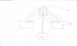
Please see my litle principle sketch below. Does this make sense? Especially the O/P to the speaker!?
I'm wondering if it makes a difference when I use the very right side output connection from the pcb instead of the centered O/P connection of the gain stage pcb.
Thanks in advance for your help!!!
Please see my litle principle sketch below. Does this make sense? Especially the O/P to the speaker!?
I'm wondering if it makes a difference when I use the very right side output connection from the pcb instead of the centered O/P connection of the gain stage pcb.
Thanks in advance for your help!!!
Attachments
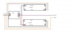
here is a drawing from the old Boards. but the conections are about the same.
the link is used just for balanced amp configuration. With a standar stereo amp the link is shorted to sig. gnd.
Is the link the only difference between SE and balanced? obviously, the inputs will be + and -, but do any parts values need to be changed?
there will be som value changes. but there is never made any schematics with values for a balanced version. as far as i know.
Like these maybe?
http://www.diyaudio.com/forums/imag...ntation/P-BAGS-1V20/P-BAGS-1V20-schematic.pdf
http://www.diyaudio.com/forums/imag...ation/P-BAGSN-1V20/P-BAGSN-1V20-schematic.pdf
http://www.diyaudio.com/forums/imag...ntation/P-BAS-S4V20/P-BAS-S4V20-schematic.zip
http://www.diyaudio.com/forums/imag...ntation/P-BAC-S4V20/P-BAC-S4V20-schematic.pdf
🙄
Wow, that's helpful! Thanks.
The BA3 FE looks a lot like the F5 FE. The BA3O like the crippled F4.... BA3 is a really nice piece!
The BA3 FE looks a lot like the F5 FE. The BA3O like the crippled F4.... BA3 is a really nice piece!
The BA-3 complementary is the greatest gift that Papa has given us - most people just haven't figured that out yet. 🙂 🙂 🙂
The BA-3 complementary is the greatest gift that Papa has given us - most people just haven't figured that out yet. 🙂 🙂 🙂
yup.
BA3 Bal , as a whole amp

The BA-3 complementary is the greatest gift that Papa has given us - most people just haven't figured that out yet. 🙂 🙂 🙂
I think a lot of people just did!

knowing his (ok , yours too ) Imusthavethemall!! approach
Lol!!!! Yes, sometimes it does seem like that... Although I only have a few more guides to do before I can settle down and actually keep something together for a few years. (My 5U chassis is currently on it's 4th amp for the guides...)
To those it may concern.
It is a pity thats not possible for those members here on diyAudio that want to build a F5T V2 on one PCB like what UKToecutter made with his layout v.1, can buy this here on diyAudio(or from any other members). I do not know of other possibilities to buy a cacode V2 PCB then what you can buy from Jims Audio.
Eivind Stillingen
It is a pity thats not possible for those members here on diyAudio that want to build a F5T V2 on one PCB
It's not a pity, because by separating the Front-end from the outputs it is possible to have one PCB set make all the different versions... V1, V2, V3, etc... Balanced in or Unbalanced, Cascode or not, Dual Jfet or not, and as many output Mosfet as you choose to implement. Doubling up on everything will let you implement fully balanced.
- Status
- Not open for further replies.
- Home
- Amplifiers
- Pass Labs
- F5 Turbo Circuit Boards