@emyeuoi
The process I refer to is Vacuum Impregnation. Basically it prevents the windings from moving excessively with the fluctuating magnetic fields induced, which is the usual cause of mechanical hum. Old style potting of the whole transfomer may also help, but I don't believe as much as Vacuum Impregnation since the latter process fills the cavities between the windings better.
The process I refer to is Vacuum Impregnation. Basically it prevents the windings from moving excessively with the fluctuating magnetic fields induced, which is the usual cause of mechanical hum. Old style potting of the whole transfomer may also help, but I don't believe as much as Vacuum Impregnation since the latter process fills the cavities between the windings better.
Anyway they are from Primerose and I suppose that they well know which kind of technic should be used to avoid the mechanical hum...
Regards,
Regards,
F5T for headphone?
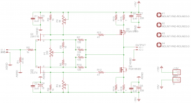
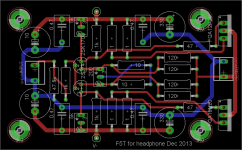
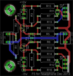
I am going to build a scale down version of F5T for headphone. For simplicity sake, (1) the current limiters are removed and (2) the thermister are also removed. But, I am not sure whether I have to retain the 2.2k resistors attached to the thermistors in the original schematic suggested by NP. 1/4W resistors will be used except R13 ~ R16, which are 1 ohm non-inductive rated at 2W. I am going to bias output at 100 ~ 150mA. Any comments on the schematic and PCB layout?
I am going to build a scale down version of F5T for headphone. For simplicity sake, (1) the current limiters are removed and (2) the thermister are also removed. But, I am not sure whether I have to retain the 2.2k resistors attached to the thermistors in the original schematic suggested by NP. 1/4W resistors will be used except R13 ~ R16, which are 1 ohm non-inductive rated at 2W. I am going to bias output at 100 ~ 150mA. Any comments on the schematic and PCB layout?
Attachments
I am going to build a scale down version of F5T for headphone. For simplicity sake, (1) the current limiters are removed and (2) the thermister are also removed. But, I am not sure whether I have to retain the 2.2k resistors attached to the thermistors in the original schematic suggested by NP. 1/4W resistors will be used except R13 ~ R16, which are 1 ohm non-inductive rated at 2W. I am going to bias output at 100 ~ 150mA. Any comments on the schematic and PCB layout?
Why don't you use 2sk2013 / 2sj313 instead of hard to get Fairchild outputs?
Probably sound better too!
Rush
????
???
By comparison the Fairchild are easy - the K2013/J313 are rapidly becoming genuine unobtanium.
Buzzforb has lots of Fairchild.
???
By comparison the Fairchild are easy - the K2013/J313 are rapidly becoming genuine unobtanium.
Buzzforb has lots of Fairchild.
Rush and 6L6
Thank you for the input.
I had done a simple research on the net before I made a post here.
I stick to Fairchild after I checked their availability and price on RS components.
Some of the alternatives are either unavailable or too expensive e.g. Toshiba 2Sk1530/2SJ201 pair.
6L6, I have ordered some Fairchild already and expect to receive them this afternoon.
Since I am not going to parallel the MOSFETs, is matching the N-P pair important?
you dont need dobble up of source resistors and feedback resistors.
but you might want to get the source resistors close to the output transistors.
you don't need TO-247 transistors. TO-220 is plenty. you can also drop C1-8.
and it is not a scaled down F5 turbo, but a scaled down F5🙂
but you might want to get the source resistors close to the output transistors.
you don't need TO-247 transistors. TO-220 is plenty. you can also drop C1-8.
and it is not a scaled down F5 turbo, but a scaled down F5🙂
you dont need dobble up of source resistors and feedback resistors.
but you might want to get the source resistors close to the output transistors.
you don't need TO-247 transistors. TO-220 is plenty. you can also drop C1-8.
and it is not a scaled down F5 turbo, but a scaled down F5🙂
AudioSan,
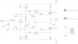
I used TO-220 footpin in the PCB for the MOSFET but did not change the FQA to FQP in schematic. Sorry for the confusion.
You are right. At low current, it may not necessary to double the resistors. I will re-allocate the position of source resistors after the deletion of the doubled resistors.
Regarding the 10u caps., they are founded in the Turbo V1 schematic in the Pass article. The 10u caps are not seen in the original F5.
Agree with you. The 330u may not be necessary. Because 100mA constant current is more than enough to drive most headphones that 300u caps are not needed for high transient load. Is my understanding correct?
and i would not drop the thermistor circut. it's there to keep the bias stable.
I am planning to mount the MOSFETs on the chasis.
I though that it can make the amp thermally stable.
Yet, adding a resistor and a thermistor is easy.
I am open here.
Since I am not going to parallel the MOSFETs, is matching the N-P pair important?
No. A good match on the input Jfets combined with the bias pots make a single N-P match not necessary.
No. A good match on the input Jfets combined with the bias pots make a single N-P match not necessary.
Sounds great. I have some matched Jfets from Spencer sitting around in my home.
F5 as a headphone amplifier?
What about reducing the gain from 6 times to 2 times?
What about replacing the vertical mosFETs with Lateral mosFETs?
Would the reduced transconductance of the Laterals balance out the increased feedback and thus not need any stability compensation?
What about reducing the gain from 6 times to 2 times?
What about replacing the vertical mosFETs with Lateral mosFETs?
Would the reduced transconductance of the Laterals balance out the increased feedback and thus not need any stability compensation?
F5 as a headphone amplifier?
What about reducing the gain from 6 times to 2 times?
What about replacing the vertical mosFETs with Lateral mosFETs?
Would the reduced transconductance of the Laterals balance out the increased feedback and thus not need any stability compensation?
1. After reading Pass article on distortion, I am curious about how F5 differs from Aleph ( I have one) sonically. And I have no experience of building power amp. So, start small and try to build a headphone amp first as a trial run.
2. 2x may be enough or may be not. There are some 600/250 ohms impedance headphones require much voltage swing.
3&4. Yes, current is not a big issue for driving headphones. You prompt me to re-read some amp design books. Good for holiday. ;p
Based on my little experience with only 4sets of headphones I suspect that all of mine would be capable of going "too loud" using a buffer as the driver.
Two times gain is an extra 6dB of SPL !
Two times gain is an extra 6dB of SPL !
If you use lateral MOSFETs the thermal issues take care of themselves. Their transconductance is much lower than the vertical mosfets, however.
and for a headphone amp, depending upon the impedance and sensitivity, you don't need that much bias current to operate in Class-A. But you will want to trim carefully to minimize DC offset.
and for a headphone amp, depending upon the impedance and sensitivity, you don't need that much bias current to operate in Class-A. But you will want to trim carefully to minimize DC offset.
- Status
- Not open for further replies.
- Home
- Amplifiers
- Pass Labs
- F5 Turbo Circuit Boards