The versions are, for the most part, differentiated by power level. Lowest power at V1 and going up. The F5T PCB in the store can be used to produce all F5T versions.OK, I am a builder and can follow a schematic, no problem. I don't really understand the details of what is happening in the amp itself so.....I see there are 3 versions of the F5 turbo. which one should I build?
You should read the F5 and F5T article by nelson pass. They will give you better insight into the amp. Read the builders guide thread also, at least till the point where discussion starts. Someone else my throw up a link to all those on here.
Great reads Airborne. I'm at work so I could only skim them enough to know I want to build the V2.
@djn
I did not read all your posts, but depending on the tube preamp and the speakers you have in the end you might be more interested (maybe) in something like the F4 or the Mofo...
Sorry I did not take the time to hyperlink to the threads, but they are on the first 2 or 3 pages of the pass forum anyway..
FWIIW,
Max
Last edited:
Great reads Airborne. I'm at work so I could only skim them enough to know I want to build the V2.
That is a logical choice. It is about as much power as you can get without breaking it into monoblocks.
I built the F5T v2 as my first ever build and had beginner's luck. There is a builder's guide by 6L6, I followed that strictly and it was a breeze, no one else has done a better one since. Love that to bits.
Great to see so many interested in building F5T.
My build took a long time researching the details. Gate resistor values. Input FET voltage dividers. Power supply transformer size. Power supply capacitor values and quantity. Power supply snubber values.
My costs were approximately $500 for DIY chassis and rear panel kit. $250 for power supply components and $250 for amplifier boards and components. About $1000 total.
Really happy with results. Replaced my class A Krell KSA 200S driving WattPuppy 5.1.
Plenty of volume without seeing any clipping when monitoring the output on a scope.
When setting bias use a scope instead of a volt meter on the output to see the direction of the output offset voltage. I did not use power supply PCB.
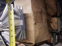
Thanks RJ. I have a chassis and heatsinks so I just need the boards, PTX, and stuffing. I just bought a pair of Full Range Field Coil drivers and hoping the F5T will drive them well.
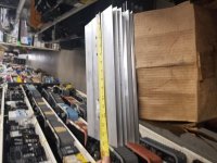
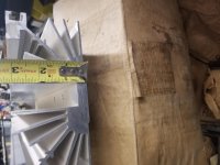
you are sure that your heatsinks are up for the task?
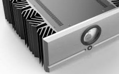
something like this would be a bare minimum:
Dissipante 4U 400mm 10mm SILVER front panel - 3mm aluminium covers and rear panel
and this one even better:
Dissipante 5U 500mm 10mm SILVER front panel - 3mm aluminium covers and rear panel
something like this would be a bare minimum:
Dissipante 4U 400mm 10mm SILVER front panel - 3mm aluminium covers and rear panel
and this one even better:
Dissipante 5U 500mm 10mm SILVER front panel - 3mm aluminium covers and rear panel
I think these will work but I'd like to get your take on it as I'm new to SS amp builds.
Attachments
Last edited:
If you got 3 of those and cut them on the midle, so you get 6 pieces at about 7.5" you would be safe. Even for some hot summer days.
And you would need 2 baseplates of around 3/8" aluminium that's 21"x7.5" or there about 🙂
And you would need 2 baseplates of around 3/8" aluminium that's 21"x7.5" or there about 🙂
Last edited:
- Home
- Amplifiers
- Pass Labs
- F5 Turbo Builders Thread