Any TO-220 NPN and PNP with the correct pin out can be used.
DO we need to do any matching on these? hFE maybe?
JT
No matching of the cascodes is needed.
I wouldn't worry too much about the 100R from emitter to drain either, unless you find you have an oscillation issue and it can't be resolved by increasing C3 & C4 or increasing output gate stoppers. If you do decide to add them in then you'll have to cut traces.
I would recommend to spend a little extra $ and get .1% or .01% source resistors (inputs and outputs) - or - if you have an accurate enough bench dvm then match them.
TJ
No matching of the cascodes is needed.
I wouldn't worry too much about the 100R from emitter to drain either, unless you find you have an oscillation issue and it can't be resolved by increasing C3 & C4 or increasing output gate stoppers. If you do decide to add them in then you'll have to cut traces.
I would recommend to spend a little extra $ and get .1% or .01% source resistors (inputs and outputs) - or - if you have an accurate enough bench dvm then match them.
TJ
Hi Takitaj,
Either cut traces or add lands for the new resistor and connection from emitter to drain I suppose. I hate cutting traces, but in this case it's probably easiest.
Does a large difference in DC offset when biasing with/without shorted RCA jacks indicate presence of oscillation?
Would oscillation be visible on scope directly from the speaker outputs?
What value of Gate stoppers or C3/C4 would you use if you detected oscillation?
If you do decide to add them in then you'll have to cut traces.IJ
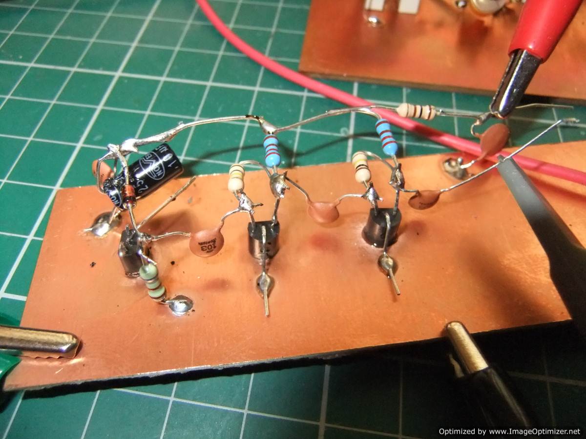
No need to do that. Bend the relevant leg of the cascode transistor up 180 degrees, now solder one leg of the resistor to it and insert the other resistor leg into the PCB hole.
nash
Everyone should build at least one really simple dead-bug circuit. It'll give you a whole new perspective. 🙂
Manhattan and Pittsburgh Electronics Prototyping Techniques — Parallax Forums
Manhattan and Pittsburgh Electronics Prototyping Techniques — Parallax Forums
No need to do that. Bend the relevant leg of the cascode transistor up 180 degrees, now solder one leg of the resistor to it and insert the other resistor leg into the PCB hole.
nash
This also gives a good test point for measuring if the cascode is working.
Hi Takitaj,
Either cut traces or add lands for the new resistor and connection from emitter to drain I suppose. I hate cutting traces, but in this case it's probably easiest.
As mentioned you can bend a lead up (cascode emitter or JFET drain) and solder one end in the hole and solder the other end to the lifted leg or lift both and solder it across there. To each his own.
When I tried it I cut the traces on the top of the board, scraped some extra back for a place to solder to and used a 1/4w Dale. The tiny blue ones that are the size of other 1/8 watters. I didn't have an issue, I did it "just in case" but it seemed like it lost some sensitivity so I built a new FE board without it. The F5T v3 requires 2 sets of output boards and only one FE per channel so I already had the second set.
I wouldn't think a DC offset at the output would indicate an oscillation. Sounds more like a bias setting issue. When you set the bias you will most likely find the N channel and P channels won't match when the offset is at zero, it's ok and is expected. Just make sure the highest channel is where you want it (~350mv) and offset is as close to zero as you can get it when hot. Different ambient air temps will affect the bias and consequentially can affect the offset. You'll probably also see a big range of offset from cold to fully warmed up. I've seen as much as 200mv at turn on, cold, and it will settle back to near zero when fully warmed up. Even when the output devices are well matched. Most match them at some certain voltage/current/temp. While they are out of that range they can differ a lot and is why curve trace matching is the ultimate. What's important is the offset is set to near zero when bias is set and amp is fully hot. You should short the input when setting bias and offset.Does a large difference in DC offset when biasing with/without shorted RCA jacks indicate presence of oscillation?
If there is an oscillation you 'should' be able to see it on the scope. May show up as a thick fuzzy trace instead of a nice crisp line. Ie: high frequency (MHz?) signal riding on the audio signal.Would oscillation be visible on scope directly from the speaker outputs?
I believe 6L6 had mentioned up to 680R. I personally increased them to 100R instead of 47R. Again, not that I had an issue, it was Just in case.What value of Gate stoppers or C3/C4 would you use if you detected oscillation?
TJ
Last edited:
Sorry, missed one.. C3 & C4 I used 1nf in all 4 positions. I believe that's what Nelson recommended in the F5T manual. He also mentions the same across feedback resistors R7,8 and R9,10. I didn't go that far, didn't need to.
TJ
TJ
What's important is the offset is set to near zero when bias is set and amp is fully hot. You should short the input when setting bias and offset.
Thanks for all the help!
The issue I had last time I tried to bias was that with input shorted, I got a certain offset. Without input shorted, I got a vastly different offset. Memory fails for an exact number.
The amp had been fully warmed up.
I am going to try to complete the amp shortly, so will keep an eye on this again.
I'll look at adding caps on the feedback as well.
I saw hardly any difference, shorted or not. The offset does change with a load though.
You are in luck, gate leakage current on your jfets are either evenly matched or incredibly low.I saw hardly any difference, shorted or not. The offset does change with a load though.
You are in luck, gate leakage current on your jfets are either evenly matched or incredibly low.
Does this difference suggest that the Jfets are damaged?
They were exposed to 40 volt rails when the cascodes failed.
I can not be sure. Some jfets are more leaky than others. 40V exposure is marginally bad for the health of the jfets but usually not fatal. I'd wait for those with more experience to chip in.
Sizes of M3 brass standoffs and M3 hex socket head
Hi All,
Is anyone so kind and can tell me the dimensions of the following parts?
M3 brass standoffs for mounting your PCBs to the chassis heatsinks
M3 hex socket head bolts for securing your your PCBs to the standoffs
M3 hex socket head MOSFET / Diode mounting bolts
fender washers for MOSFET / Diode mounting
thank you so mutch
You have the M3 on most of the stuff, I suggest you order it form DIY and not worry about it...
JT
Does this difference suggest that the Jfets are damaged?
They were exposed to 40 volt rails when the cascodes failed.
Does anyone know why using shorting plugs produces different bias currents?
I am going to try to get my amp up and running this week and want to know how to avoid this problem if it shows up again.....
Does anyone know why using shorting plugs produces different bias currents?
I am going to try to get my amp up and running this week and want to know how to avoid this problem if it shows up again.....
It reduces extraneous signals which result in improper bias adjustment, at the least your are chasing a ghost because the reading with fluctuate while you are trying to adjust it.
IIRC, the difference in bias voltage was on the order of 300 mV. I'll let you know what I see here, later this week.
One key difference in this iteration of the amp, is that I am using IRFP devices, not Fairchild. OTOH, there may have been issues with the cascode at the time....
One key difference in this iteration of the amp, is that I am using IRFP devices, not Fairchild. OTOH, there may have been issues with the cascode at the time....
Last edited:
I did some MOSFET matching last night, and made some kits up.
Matched IRFP240 + IRFP9240 MOSFETs + F5 Turbo Kits
Matched IRFP240 + IRFP9240 MOSFETs + F5 Turbo Kits
- Home
- Amplifiers
- Pass Labs
- F5 Turbo Builders Thread