@BigE
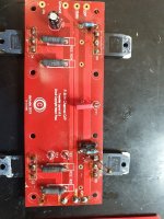
I drilled them out as well, The pads are big enough to do so, I read where the holes were intended to be larger, but the mistake wasn't caught. The fear was that drilling them would cause a pad to rip, or come loose. I used a high speed drill and very little pressure. It worked like a champ and thee is no need for wire trick, or header pins etc. All the holes except the gate were drilled to accept up to 14 gauge wire.
This is after the first hole drilled, see the one ground hole which is larger. Sorry for the blurry photo.
Make sure you solder the wire on both sides of the PCB since the thru hole plating is now removed.
nash
Make sure you solder the wire on both sides of the PCB since the thru hole plating is now removed.
nash
Yes, I have done so. 🙂
Thanks
*Note: When you drill out the holes to use larger wire there is something else to consider. The top pad, or bottom, depending on the board layout, become isolated from the circuit. In other words, the only connection for the opposite side pads, is the through hole. Once you remove that , you will loose that sides contact with the circuit. This being the case, I suggest you do not drill the boards.
When you flow solder through the hole and solder both sides that connection is reestablished, but...., again, I would not advise this procedure. If I only had eye where my rectum is... 🙂
JT
When you flow solder through the hole and solder both sides that connection is reestablished, but...., again, I would not advise this procedure. If I only had eye where my rectum is... 🙂
JT
Last edited:
Soldering the wiring direct in place assumes it will work perfectly the first time.
I drilled the same holes on the FE board but mounted them with a male spade connector, making disassembly possible.
Sadly, the holes on the output boards don't line up.
I drilled the same holes on the FE board but mounted them with a male spade connector, making disassembly possible.
Sadly, the holes on the output boards don't line up.
Soldering the wiring direct in place assumes it will work perfectly the first time.
I drilled the same holes on the FE board but mounted them with a male spade connector, making disassembly possible.
Sadly, the holes on the output boards don't line up.
The flexibility of the board leaves a lot of options. I considered taking the output off the board closest to the front, ground and output right there. Is there something with pulling the output across both boards that makes it better to pick it up from the FE board? I have them on the FE, but it would be neater and shorter the other way.
If you have the clearance, after drilling, replace the through hole plate; copper or brass, available in many sizes.
That is a welcome comment... I love the idea, and had not thought about the option! Let's hope the next time. if ever, the PTB, correct the issue....

Last edited:
The flexibility of the board leaves a lot of options. I considered taking the output off the board closest to the front, ground and output right there. Is there something with pulling the output across both boards that makes it better to pick it up from the FE board? I have them on the FE, but it would be neater and shorter the other way.
The FE board needs a feedback signal.
I've got a terminal strip that connects output to speaker post, and another line to FE board, thus avoiding any high currents flowing near the FE board.
At least, that's what is supposed to happen -- not completed, but hopefully soon.
If you have the clearance, after drilling, replace the through hole plate; copper or brass, available in many sizes.
Plain old through hole rivets?
Yup, copper preferred, not much chance of ripping one out after it's soldered.
Alternatively, use the largest piece of TC wire that will fit the hole, form it into a ? shape and close the loop, solder your new horizontal eyelet into the PCB.
Alternatively, use the largest piece of TC wire that will fit the hole, form it into a ? shape and close the loop, solder your new horizontal eyelet into the PCB.
Here's the deal.... one side matters not at all after drilling. Well, I guess it might for stability, but there is no contact there, so it doesn't mean squat. Yes, the solder flow may reconnect it, but the only trace that matters, has been limited to one side; Not only that, it has been reduced from drilling.
Here's the thing... you want to drill to increase the DIA of wire size you may use, but in doing so, you reduce the contact surface by less than half. Do your own maths. The bottom line is you are better using a cut down wire, and soldering the base of said wire to the pad than you are drilling. At the very least it's a wash.
I did some testing after I drilled, there was only one side of the pad making contact with the trace. That said, soldering from both sides makes ZERO difference other than the stability.
FWIW
JT
Last edited:
I did some testing after I drilled, there was only one side of the pad making contact with the trace. That said, soldering from both sides makes ZERO difference other than the stability.
FWIW
JT
Yes from the stability standpoint. If you do not, there is a strong likelihood that when you move the board after the wire is soldered on, you will lift the pad and the trace along with the wire.
nash
Hi all. First time reading this thread...(difficult for F5T beginnes getting the basic information)
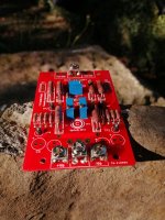
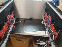
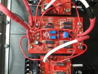
Trying to rescue a F5T (dual mono). Not the prettiest built I have seen. But after I have finished I assure you it will be fine 🙂 It will be torn apart and rebuilt.
It looked like a rats nest so I guess something shorted one time....
It is still in dissassembly mode and of course a couple of FQA19N20c transistors have gotten wings.
Any chance of getting new(old) ones anywhere that are not ebay fakes?
Sincerely
Magnus
Attachments
Hi all. First time reading this thread...(difficult for F5T beginnes getting the basic information)
Trying to rescue a F5T (dual mono). Not the prettiest built I have seen. But after I have finished I assure you it will be fine 🙂 It will be torn apart and rebuilt.
It looked like a rats nest so I guess something shorted one time....
It is still in dissassembly mode and of course a couple of FQA19N20c transistors have gotten wings.
Any chance of getting new(old) ones anywhere that are not ebay fakes?
Sincerely
Magnus
I'm working on a V2 build now and I looked, but didn't find anything I would trust. Many of use have subbed the IRFP240P and 9240. Which are also obsolete however, there are still some available.
@bambadoo
The entire build and parts are suspect, I would replace anything I wasn't 100% on. It's better to do it now than to have an issue later. The parts cost doesn't justify the risk.
The newbs, 2 pence.
JT
The entire build and parts are suspect, I would replace anything I wasn't 100% on. It's better to do it now than to have an issue later. The parts cost doesn't justify the risk.
The newbs, 2 pence.
JT
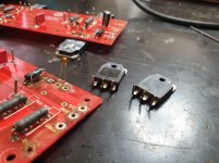
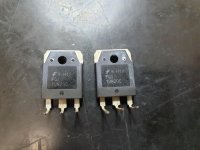
They look similar to what I've seen before.
See if the dimensions match those on page 7:
https://www.promelec.ru/pdf/FQA19N20C.pdf
See if the dimensions match those on page 7:
https://www.promelec.ru/pdf/FQA19N20C.pdf
- Home
- Amplifiers
- Pass Labs
- F5 Turbo Builders Thread