Amp has a star GND which is connected to the Chassis via a NTC. see pic 1
I did remove the PSU and BA-3 FE and now the noise is reduced to a level that it is barely audible at listening position. But still there is a little noise. Again disconnected Pre the F5T is silent
Nils
Have you tried 10 ohm between input gnd and common gnd?
What's up with that grey wire between the transformer and the front plate? Looks like it's forming a loop at first glance.
Thanks all for the replies
The Grey wire is actually white and is coming from SoftStart going to the DC blocker. DC blocker did not reduce the hum. from DC blocker into the transformer.
@ AnrewT: Isn't the StarGND the MAG?!? Thought that all GND connections should go to star and from there to the chassis. How can I make a MAG? it is a new concept for me! I'm not Electronically educated.
On pos and neg rail there is a 25 W resistor .47Ohm. Bleeder resistors are accidentally 20K. Should be 2K2 (I just Noticed ) AudioSan was right with naming the wires
Maybe a noob question: what do you mean with "The audio reference".the 2 bare leads are the bleeder resistors. 1G/Y is chassis ground. the 2 white close to the transformer is from the bridges. the 2 whites at the center is from the amp boards. the 2 blue are speaker return.
it's all good.
and referring to the wire question of post #4070 should the blue (speaker return) go to the output boars as the speaker hot wire?
@ AudioSan: I did not yet try the Big fat wire between the RCA-gnd. previous I also tried to disconnect the RCA-return and connected this to the star. No luck there.
Nils, did you try disconnecting one of the RCA GNDs?
Did tha earlier, no difference as I can recall.
Thanks again, quest continues.
Nils
Many of the hum problems stem from running single wires to the terminals, or between modules.
Many more hum problems stem from locating the AUDIO reference on the PSU Zero Volts connection.
If one eliminates both these errors in wiring, then one would be hard pushed to find any enquiries on this Forum about Hum and Buzz.
Separate the Safety connections form the Audio connections.
Make all inter module connections a proper two wire Flow and Return.
Safety is:
PE to Chassis
and
The fuse blowing connection from Chassis to MAG/PSU Zero Volts/SpeakerReturn terminal.
Any of these alternatives can be used, since all use heavy wires that can pass Fault current, if there is a catastrophic mains failure inside the closed box.
Last edited:
Thanks all for the replies
The Grey wire is actually white and is coming from SoftStart going to the DC blocker. DC blocker did not reduce the hum. from DC blocker into the transformer.
@ AnrewT: Isn't the StarGND the MAG?!? Thought that all GND connections should go to star and from there to the chassis. How can I make a MAG? it is a new concept for me! I'm not Electronically educated.
On pos and neg rail there is a 25 W resistor .47Ohm. Bleeder resistors are accidentally 20K. Should be 2K2 (I just Noticed ) AudioSan was right with naming the wires
Maybe a noob question: what do you mean with "The audio reference".
and referring to the wire question of post #4070 should the blue (speaker return) go to the output boars as the speaker hot wire?
@ AudioSan: I did not yet try the Big fat wire between the RCA-gnd. previous I also tried to disconnect the RCA-return and connected this to the star. No luck there.
Did tha earlier, no difference as I can recall.
Thanks again, quest continues.
Nils
you can try with a test wire with crocodile clamps between the 2 RCA Jack GND Points. just to see if it makes much difference.
also, if you pull out one of the RCA cables the noise should be gone.
Last edited:
you can try with a test wire with crocodile clamps between the 2 RCA Jack GND Points. just to see if it makes much difference.
also, if you pull out one of the RCA cables the noise should be gone.
pulling one out was not helping unfortunately!! and connecting bothe RCA Jack GND was also not lowering the noise. Although I think I found part of the nois source! RCA Cable (glasshouse interconnect No. 7).
Think it is a bit strange it makes the Amp hummm becaus I checked for shortened wires. Not present!
Is it that sensitive it's picking up noise? Weaving method?
Nils
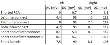
test in stages.
Short the inputs with zero ohm dummy plugs.
Measure the output offset and the output Noise+Hum using a 199.9mVac or dc scale.
insert one interconnect leave the remote end open. re-measure the dc & ac
insert the other interconnect , remeasure.
insert BOTH interconnects, still both open, remeasure.
Short each interconnect pole to barrel, remeasure.
Short the barrels of the two interconncts together, remeasure.
test in stages.
Did some measurements! First had to alter offset. this was driftes away from near 0.
following are the measusrements:
There is a AC intoduces by the interconnects. bit strange though
Nils
Attachments
Last edited:
your results confirm that a stereo interconnect cause a loop problem (last test, loop barrels). There is another problem revealed by the results, but I'm not sure what it is.
Look at Left interconnect (open ended) and see the different effect on L & R outputs. Why?
Then swap to Right and a similar effect, but reversed.
I can't understand why the DC output offset changes on the channel that has no cable connected.
Then you have 8.8mVac on the right when the left interconnect is shorted. why?
I think this points to a wiring error and possibly a component value error, or soldering error.
Last edited:
The open ended interconnects act as aerials to the respective inputs. The input sees the 100k, or whatever, and a long wire.
The screen/shield has no effect, despite what folk tell you about the magical properties of coaxial cable.
The long open ended interconnect will pick up interference and the amplifier will multiply the "in Band" part of that to be read as an output AC voltage.
The screen/shield has no effect, despite what folk tell you about the magical properties of coaxial cable.
The long open ended interconnect will pick up interference and the amplifier will multiply the "in Band" part of that to be read as an output AC voltage.
Andrew, thanks!
"When the student is ready, the teacher will appear". This was my time to be ready to understand this phenomenon and there you were explaining it!
"When the student is ready, the teacher will appear". This was my time to be ready to understand this phenomenon and there you were explaining it!
No idea. Shortened RCA gave good values. However open RCA gives values shown in table as not connected. 110mVACyour results confirm that a stereo interconnect cause a loop problem (last test, loop barrels). There is another problem revealed by the results, but I'm not sure what it is.
Look at Left interconnect (open ended) and see the different effect on L & R outputs. Why?
Here I did leave the right IC sitting. Values measured only left IC connected and shortened end did not alter values. So this measurement was the same as open ended right IC connected.Then you have 8.8mVac on the right when the left interconnect is shorted. why?
But still the Amp is Silent without any IC connected. Once a interconnect is attached is starts making noise. interconnect depended!I think this points to a wiring error and possibly a component value error, or soldering error.
I'm getting a bit puzzled now!
Oh, and the interconnects are very sensitive antenna's
 ?
?Yes, that's why we NEED a low Source impedance attached to the remote ends.the interconnects are very sensitive antenna's
It is also why when using switched inputs we don't inadvertently leave an unconnected lead attached to a live (amplfying) input.
The open RCAs are loaded by the RF filter and that filter has a very low impedance at RF frequencies. thus we don't hear much noise. It is measureable.
It's the measurements that objectively confirm that you are making the correct adjustments to get the wiring more correct.
Don't use your ears as measuring instruments !
With open input RCAs, attach a shorting link between the barrels. Does the H+N change?
With Shorted inputs (dummy zero ohms RCA plugs) and shorting the barrels, does the H+N change?
I have no enough time to thoroughly examine pictures you sent , so I'll give you final patch (not real thing - proper wiring etc ) :
put fat and shortest (you can achieve) bridge between two signal gnds** on channel pcbs
so - one fat wire from left to right
that way you'll kill any potential differences between signal gnds in most sensitive area
** point where input cables are connected
put fat and shortest (you can achieve) bridge between two signal gnds** on channel pcbs
so - one fat wire from left to right
that way you'll kill any potential differences between signal gnds in most sensitive area
** point where input cables are connected
pulling one out was not helping unfortunately!! and connecting bothe RCA Jack GND was also not lowering the noise. Although I think I found part of the nois source! RCA Cable (glasshouse interconnect No. 7).
Think it is a bit strange it makes the Amp hummm becaus I checked for shortened wires. Not present!
Is it that sensitive it's picking up noise? Weaving method?
Nils
Have you tried other interconnects? coaxial type? The glasshouse....I don't know....
Are your interconnects shielded type? The longer the interconnects the more noise will be picked up. They are indeed "sensitive antenna" like Andrew T says. Try different type of interconnects.
Are your power cords shielded? Your interconnects may be picking up noise from the power cord.
Nash
Are your power cords shielded? Your interconnects may be picking up noise from the power cord.
Nash
All my power cords are standard mains cable type.
They have a mild twist for the triplet (L+N+E).
These do not emit as much emi as untwisted 2core mains cable (L+N).
They have a mild twist for the triplet (L+N+E).
These do not emit as much emi as untwisted 2core mains cable (L+N).
put fat and shortest (you can achieve) bridge between two signal gnds** on channel pcbs
so - one fat wire from left to right
Zen Mod, it did reduce noise drastically. Now I have to put my ear at 5 cm distance from speaker to hear some noise. Did not measure yet.
Will do this somewhere this weekend or coming week.
Thanks all for input!
I have a stupid question.. The MUR3020W that are across the source resistors in the F5 turbo v2.. What would stop you putting them across any emitter or source resistor that, at idle, wouldn't cause it to conduct.. to effectively get rid of their current limiting effects? I am considering building the DOGC-H which runs its outputs in almost no standing current.. So could adding such diodes in similar positions afford some benefit here?
p.s. The schematic for this is here..
http://bas.elitesecurity.org/DOGC-H sema.gif
p.s. The schematic for this is here..
http://bas.elitesecurity.org/DOGC-H sema.gif
Last edited:
..and I suppose a follow-up question; effectively bypassing the source resistors at currents much greater than idle.. does this then negate the current sharing effects of those resistors too? So that you then might have to closely match the output devices? And does this make this kind of trick/topology only good for certain kinds of output devices? I've never seen anything like this before you see.. so I wonder at whether it's an effective tweak for existing designs or fraught with danger.. 
Last edited:
If you dump the entire rail of that amp into the shown load (less 3V for the BJT), the drop across each emitter resistor is 0.6V, give or take.
I don't see the point of attaching the diodes there. I think this is primarily for when you need high source resistors for design reasons, but still need very high currents.
I don't see the point of attaching the diodes there. I think this is primarily for when you need high source resistors for design reasons, but still need very high currents.
- Home
- Amplifiers
- Pass Labs
- F5 Turbo Builders Thread