Because I trust you people more than I trust the famous chinese vendor (no offense intended) 🙂
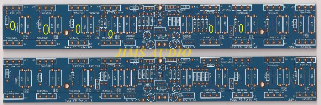
The board say +/-32 but I thought that the topology/design of the turbo v3 could allow for much higher voltages. Am I wrong?
The board say +/-32 but I thought that the topology/design of the turbo v3 could allow for much higher voltages. Am I wrong?
I know what's written & drawn in article , but I really don't know anything about pcbs you're having
cascoded FE with appropriate resistor values for highish PSU is what's relevant
you need to have no more than 15V across input jfets
if you have place on pcb for that , you're good to go
cascoded FE with appropriate resistor values for highish PSU is what's relevant
you need to have no more than 15V across input jfets
if you have place on pcb for that , you're good to go
Thank you for your reply. I read what is written on the diyaudio store and saw what you meant...
CASCODE FORMULA: rail voltage / (R26+R28) * R28 = cascode voltage
ex: 50V rails / (10Kohm+4,75Kohm) * 4.75Kohm = 16.1V
CASCODE FORMULA: rail voltage / (R26+R28) * R28 = cascode voltage
ex: 50V rails / (10Kohm+4,75Kohm) * 4.75Kohm = 16.1V
Hey all,
I am still having issues with one channel of my F5T. I can get it biased up fine but it just drifts down. It's slow but steady. If I shut it down for a bit and turn it back on the bias jum
I am still having issues with one channel of my F5T. I can get it biased up fine but it just drifts down. It's slow but steady. If I shut it down for a bit and turn it back on the bias jum
Hi All,
I am still having issues. I can bias on channel perfectly. The other drifts down over time. If biased at 0.3vdc it will drift down to 0.2vdc within 30min and contine down. I have it cooking now to see how low it will go. If I bias up agin it begins to drift more. If I shut it down for a bit it jumps back to 0.3vdc and begins to drift down.
I am still having issues. I can bias on channel perfectly. The other drifts down over time. If biased at 0.3vdc it will drift down to 0.2vdc within 30min and contine down. I have it cooking now to see how low it will go. If I bias up agin it begins to drift more. If I shut it down for a bit it jumps back to 0.3vdc and begins to drift down.
if mosfets are correctly mounted to correctly sized heatsinks and they're part of properly ventilated case .......... then I really don't have idea what's wrong
use 39K and 12K (max. 15K)
Thanks!
What is the safe voltage upper limit using this trick? Would you think that +/- 100v is doable (given adequate heatsinks etc.)?
Hi ClassZ,
Changing PS voltages has been discussed a couple of times. If you go back to page 324 I asked about it again as a newbie to this forum. If you start reading from there you will see some interesting info from these good people. I will be using a 48v PS when I finally get around to the F5 turbo project (still playing with making a longer chassis for a threshold SA/1 clone and beefing up the PS to 2.4kva and .544 farads of caps). 🙂
The idea of running with 100v PS rails is interesting if you are interested in more power but the PS Caps are going to cost you. I also had the idea of using some of the new Silcon Carbide BJTs for outputs but they are too expensive yet.
Have a good one,
John

sissy amp, he he he, good one. Actually I think the SA/1 was one of the finest amps Nelson produced...until he started Pass Labs and made some greater stuff. I have placed the SA/1 up against some of the best amp around and other than the barely noticeable sibilants of the BJT over MOSFETs it has clean open sound. My beefing up the PS isn't really nessessary but it is what DYI audio people do, overkill.
The F5 Turbo's simplicity of the front end intrigues me, a good vehicle for experimentation, the push-pull output is pretty standard. The SA/1 had 40 output BJT so it was very robust.
Have a good one,
John
The F5 Turbo's simplicity of the front end intrigues me, a good vehicle for experimentation, the push-pull output is pretty standard. The SA/1 had 40 output BJT so it was very robust.
Have a good one,
John
Hi ClassZ,
I will be using a 48v PS when I finally get around to the F5 turbo project (still playing with making a longer chassis for a threshold SA/1 clone and beefing up the PS to 2.4kva and .544 farads of caps). 🙂
John
Just make sure you have a very robust slow charge circuit.... that was probably my biggest headache with the F5TV3 build.
Hi Dazed2,
I have two designs for soft start circuits, one automatic and one manual, uses big thermistors and cutout relays, NE555 for relay put in. With the original 116,000 uf caps the amp needed the softstart, at 5 times the cap storage it will definately need the softstart.
I have two designs for soft start circuits, one automatic and one manual, uses big thermistors and cutout relays, NE555 for relay put in. With the original 116,000 uf caps the amp needed the softstart, at 5 times the cap storage it will definately need the softstart.
- Home
- Amplifiers
- Pass Labs
- F5 Turbo Builders Thread