Hi Eivind,
Sangram is correct, I forgot to include the current through the feedback resistors R7-10. Without actually measuring it to know, I am guessing here, I calculate 42.5v/120ohms is .35A so 3.5W resistor, although you will not have that much current in actual operation and not continuous so a 3w 10ohm might be fine. the .25w will not be fine. 🙂 Also I would still like to know with 42.5v rails what are your values for R5 and R6, also R25 and R26. I am trying to see what others have done with different supply voltages.
Thanks,
John
Dazed2,
You are running 53 volt supply rails. What are your values for R5 and R6, also R25 and R26. Again, I am trying to see what others have done with different supply voltages, what changes are necessary.
Thanks,
John
You are running 53 volt supply rails. What are your values for R5 and R6, also R25 and R26. Again, I am trying to see what others have done with different supply voltages, what changes are necessary.
Thanks,
John
Dazed2,
You are running 53 volt supply rails. What are your values for R5 and R6, also R25 and R26. Again, I am trying to see what others have done with different supply voltages, what changes are necessary.
Thanks,
John
R5and 6 is 1K
R25-26 I use 12K
Thanks to Dazed2 and Eivind for your info. I have the PCB so once I find some time I will experiment the different rail voltages and taken voltage and current reading at most of the points on the board, starting with the stock 32v and resistors and then modify the supply voltage and see just how much effect on the circuit and what resistor changes might be needed to keep the FETs in the same operating zone.
Thanks again,
John
Thanks again,
John
Remember the basic rules of transistor life in a pass amp...
No more than 30ish volts across the Jfets, 24 is better.
Heatsink Max.Temp 55C, Mosfet max.temp pin 2 65C
Max bias of 1/2 the Mosfet rated maximum in W -- look at the the temp derating curves on the datasheet!
Bias the entire amp (in total W) no more than 1/2 the VA of your transformer
No more than 30ish volts across the Jfets, 24 is better.
Heatsink Max.Temp 55C, Mosfet max.temp pin 2 65C
Max bias of 1/2 the Mosfet rated maximum in W -- look at the the temp derating curves on the datasheet!
Bias the entire amp (in total W) no more than 1/2 the VA of your transformer
Hi dazed2 and Eivind,
So Eivind is using the original resistor values. I am curious about what voltage both of you see across R27. And did you make any other resistor value changes anywhere else in the circuit to handle the higher supply voltage.
Thanks,
John
So Eivind is using the original resistor values. I am curious about what voltage both of you see across R27. And did you make any other resistor value changes anywhere else in the circuit to handle the higher supply voltage.
Thanks,
John
Hi dazed2 and Eivind,
So Eivind is using the original resistor values. I am curious about what voltage both of you see across R27. And did you make any other resistor value changes anywhere else in the circuit to handle the higher supply voltage.
Thanks,
John
With my rail voltage and 12K at R25/26 I get about 15.87V at R27 feeding the jfets. Those jfets are supposed to work really nicely between 12-16V, so thats why I decided to up the value of R25/26 from stock.
Other than that I decided to up the feedback resistor more so I get more gain. Instead of 110ohm at the feedback I'm using 200ohm. Otherwise everything else is as per schematic.
Thanks dazed2, I calculated around 15v on your circuit so it is nice to know it is close. The stock circuit shows about 10.3v across R27 which biases the base of Q7. So we have a range of 10.3v to 15.87 so far for bias to the cascode transistor. I calculated 2 ma through R27 in stock form and 3.3ma on youir circuit. I will start with 14K for R27 for a 48v supply voltage and try all the way up to 18k on R27 which maintains stock voltage and current on R27 and see what actual voltage differences are on the FETs.
Thanks,
John
Thanks,
John
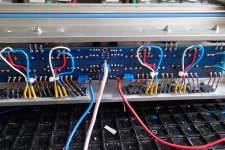
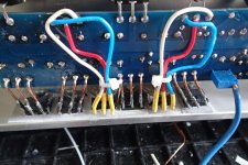
The damage after R3/4 burned show up to be quite worse. I took my time to test all power FETs. Six out of 8 power FETs was broken(no MUR diodes). Since I use a cooling tunnel and mounted the powe FETin an unusual manner, it was a hell of a job. I will wait til to morrrow to fire it up again. I dont want to hurry into new troubles. I do have learn to walk slowly and to double check.
Johnhenryharris: Interesting project modding F5 with different powersupplies.
The tunnel I use are separated into four "individual" heatsinks not connected to each other. This result in a much lesser spread of the heat. I started with all the power FETs on the upper heasink and the diodes on the lower. Now I have moved four of the FETs together with all the diodes. This have lowered the temperatur very much. My aim is to run with 310mV over sources or so much the tunnel can take keeping the temperatur around 50 C. I also use blowers on a very slow run.
Eivind Stillingen
Attachments
Last edited:
Heatsink size
Hi I wonder how big my heatsink need to be. I have 2 off theese. Have bought F5 turbo V 3 with 4 sets off mosfets on each channel running on 29 vdc Will the heatsink be ok ??? `
| 1500HS02000DU, Birmingham Aluminium | Wattbits
Hi I wonder how big my heatsink need to be. I have 2 off theese. Have bought F5 turbo V 3 with 4 sets off mosfets on each channel running on 29 vdc Will the heatsink be ok ??? `
| 1500HS02000DU, Birmingham Aluminium | Wattbits
2 of those heatsinks should be proper for a monoblock v3.
I was afraid off that.
 I will use 2 fans for each mono as well then 😱
Are we sure? They are 11.8" x 7.87" x 1.57" each. 11.8"x25.4= ~300mm
From the Store:
"The 5U 400mm contains four heat sinks and each is rated at 0.28 C/W"
One 5U chassis is good for Mono-block F5T v3.
From the Store:
"The 5U 400mm contains four heat sinks and each is rated at 0.28 C/W"
One 5U chassis is good for Mono-block F5T v3.
The "four" heatsinks should be more accurately be though of as (2) heatsinks each composed of two pieces.
Large Heat Sink For Power Transistor/MOSFET/IC TO-3/TO-126/TO-220/TO-247.. | eBay
I bought 4 heatsinks 80x78x35 mm to mount on the inside off the big heatsink.
I bought 4 heatsinks 80x78x35 mm to mount on the inside off the big heatsink.
FYI
Mouser: May 29, 2014
You have purchased the following part number(s) from Mouser Electronics within the last two years. The manufacturer has published a Product Change Notice. Please click on manufacturer part number to view product details and similar products for replacements.
PURCHASED:
MANUFACTURER PART# MOUSER PART# PO# DOCUMENTS
ON Semiconductor MUR3020WTG 863-MUR3020WTG 7319703 PCN: Final Product / Process Change Notification
MUR3020WTG ON Semiconductor | Mouser
Hello everyone,
just a quick question on the F5 turbo v3. 🙂
I have purchased the board on the internet (famous chinese vendor) and was hoping to run the f5 turbo v3 on +/- 54v right out of the board. The reason is that I have a very good smps power supply which should prove adequate for audio use.
I have excellent heatsink with forced air cooling.

Can the board take the voltage, are there any requirements in terms of parts that I should be aware of?
Thanks to all for your help.
ClassZ
just a quick question on the F5 turbo v3. 🙂
I have purchased the board on the internet (famous chinese vendor) and was hoping to run the f5 turbo v3 on +/- 54v right out of the board. The reason is that I have a very good smps power supply which should prove adequate for audio use.
I have excellent heatsink with forced air cooling.
Can the board take the voltage, are there any requirements in terms of parts that I should be aware of?
Thanks to all for your help.
ClassZ
- Home
- Amplifiers
- Pass Labs
- F5 Turbo Builders Thread


