Another question... Does anybody know where to buy great looking aluminium amplifier feets ???
Another question... Does anybody know where to buy great looking aluminium amplifier feets ???
May be this could help you, [no affiliation]
"bestücken" yeah..terminalblock
Aderendhülsen, with the proper type of crimping pliers.
Or solid connector pins with a solder sleeve.
(prettiest for terminal block connections are pressed-on pins, but that's out of diy range)
"Feets" is a fleet of feet.

Last edited:
Aderendhülsen, with the proper type of crimping pliers.
Or solid connector pins with a solder sleeve.
(prettiest for terminal block connections are pressed-on pins, but that's out of diy range)
"Feets" is a fleet of feet.
pic? I was going to start using pcb mount blade connectors, with option for direct solder.
Pic of what, end sleeves or pliers ?
An end sleeve should be crimped in one go, and with very high pressure on the sleeve, which requires a lever type crimping tool.
Self adjusting ones by Phoenix contact or Knipex cost a few hundred dollars, but a China copycat can be had for $20, e.g. at the bay.
No idea how long those will last, but I'd think at least a few dozen amp projects.
Standard crimping pliers are junk.
Don't use terminal blocks, problem solved.
Alternative for modular building is spreading the connector tabs further apart at the board design stage.
(or additional tabs, still remains difficult to suggest/ask for at GB efforts)
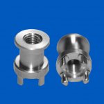
There are serial manufacture metal blocks for PCB mounting, either with multiple solder pins, or a threaded end.
Mounting side is either a screw hole, or also a threaded end for a nut.
Smallest ones are 0.2''/5mm diameter, see example pic, rectangular ones are 9/32'' .
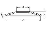
Smallest disc spring is 6mm diameter, also see example pic.
For an M3 ring cable lug : mounting block - cable lug - regular washer - disc spring - screw head.
Alternative for modular building is spreading the connector tabs further apart at the board design stage.
(or additional tabs, still remains difficult to suggest/ask for at GB efforts)
There are serial manufacture metal blocks for PCB mounting, either with multiple solder pins, or a threaded end.
Mounting side is either a screw hole, or also a threaded end for a nut.
Smallest ones are 0.2''/5mm diameter, see example pic, rectangular ones are 9/32'' .
Smallest disc spring is 6mm diameter, also see example pic.
For an M3 ring cable lug : mounting block - cable lug - regular washer - disc spring - screw head.
Attachments
Last edited:
My last pic with the green terminalblock...what is better? Tinned leads, or just with the bare copper leads ???
What gives the lowest contact resistance? Also in long term?
Or should I not use them at all, and solder the leads directly on the PCB's?
But then my PSU is not so modular anymore😕
Walter
Walter, I solder directly to the boards. I hate those terminal blocks--adds to the "clutter" of a clean chassis (yours is.....!) and just becomes another potential spot for trouble.
I can't tell from your photos..... Do you have rubber grommets in your chassis holes, where you run your power supply/transformer leads from on side of the chassis to the other. If not, you might want to consider them--they are a cheap insurance for potential "high current to ground" problems later.
If you have already done the final wiring, I possible solution to still install a grommet--slice a suitable rubber grommet somehere on it's circumfrences (so you have a "C" rather than a full "O") and work the grommet into the hole around the chassis (using a small flat-blade screwdriver). With the proper grommet for the hole, the "C" should close back into an "O". Not a perfect solution, but close enough.
Making some progress...
My last pic with the green terminalblock...what is better? Tinned leads, or just with the bare copper leads ???
What gives the lowest contact resistance? Also in long term?
Or should I not use them at all, and solder the leads directly on the PCB's?
But then my PSU is not so modular anymore😕
Walter
Walter -
Your question is a good one. Up until lately I worked in a test lab testing electrical connectors. When you have a lot of pressure on the wire, like from a tightened down screw, it does not really make any difference if the wire is tinned, bare copper or even gold plated for long term conductivity. If the pressure is a lot lower, say under 100 grams, like in many connectors, then the plating matters much. I speak from experience subjecting connectors to acid vapor, thermal cycles, humidity cycles, etc. The Phoenix brand of green connector seems to be a very good one. The thing I suggest is to twist the strands on the end so they do not flatten, then tighten the screw, then wiggle the wire and tighten again until it won't tighten any more.
All that being said...if I do not need something to be modular or easily disconnected in the future, I solder my connections, making sure there is not any stress on the solder joint.
Hi was just wondering, whats the word on VU meters ?
would they lower the sound quality ?
im planning on using this one on a seperate 2x 12v winding
1x New High quality stereo Driver PCB board for Panel VU meter | eBay
one of the 12v being for the VU meter and the other winding for the B1.
and the 2x24v for F5T
Any comments welcomed!
would they lower the sound quality ?
im planning on using this one on a seperate 2x 12v winding
1x New High quality stereo Driver PCB board for Panel VU meter | eBay
one of the 12v being for the VU meter and the other winding for the B1.
and the 2x24v for F5T
Any comments welcomed!
Walter -
Your question is a good one. Up until lately I worked in a test lab testing electrical connectors. When you have a lot of pressure on the wire, like from a tightened down screw, it does not really make any difference if the wire is tinned, bare copper or even gold plated for long term conductivity. If the pressure is a lot lower, say under 100 grams, like in many connectors, then the plating matters much. I speak from experience subjecting connectors to acid vapor, thermal cycles, humidity cycles, etc. The Phoenix brand of green connector seems to be a very good one. The thing I suggest is to twist the strands on the end so they do not flatten, then tighten the screw, then wiggle the wire and tighten again until it won't tighten any more.
All that being said...if I do not need something to be modular or easily disconnected in the future, I solder my connections, making sure there is not any stress on the solder joint.
Ah thanks! That's the answer I was looking for.
I liked the idea to exchange Amp boards so I can try different Amps. But maybe I just solder the connections anyway...
Walter, I solder directly to the boards. I hate those terminal blocks--adds to the "clutter" of a clean chassis (yours is.....!) and just becomes another potential spot for trouble.
I can't tell from your photos..... Do you have rubber grommets in your chassis holes, where you run your power supply/transformer leads from on side of the chassis to the other. If not, you might want to consider them--they are a cheap insurance for potential "high current to ground" problems later.
If you have already done the final wiring, I possible solution to still install a grommet--slice a suitable rubber grommet somehere on it's circumfrences (so you have a "C" rather than a full "O") and work the grommet into the hole around the chassis (using a small flat-blade screwdriver). With the proper grommet for the hole, the "C" should close back into an "O". Not a perfect solution, but close enough.
Propitious thanks for the tip, I have been looking for rubber grommets about 13-14 mm diameter with a height of 5 mm ( 3mm alu + 2 mm steel), but didn't find them that high.
exchange amp boards
Or have a 2nd soldered connection at a distance from the boards.
Solder short wires to the pads of the boards, solder the other ends at a solder terminal block. (those are sold with a plastic cover, insulation and looks pretty)
(Tülley me dürch : Hellermann : HV1206 + HV1304. Sold everywhere, Conrad etc.)
(Tülley me dürch : Hellermann : HV1206 + HV1304. Sold everywhere, Conrad etc.)
Ah, thanks! I understand.
Than I solder my connections first, and when I want to switch boards, I can always do that trick 🙂
Than I solder my connections first, and when I want to switch boards, I can always do that trick 🙂
Guys, I realy could appreciate any advice on speaker protection circuit that is suitable for this amp ? how about the DIYaudio ones ? or any others, with soft start would be nice.
- Home
- Amplifiers
- Pass Labs
- F5 Turbo Builders Thread