Well, many many many many thanks to Jim who talked me through the bias procedure which is not nearly as scary as I thought it would be.
And he started with a very good analogy - basically don't spill the beer!!
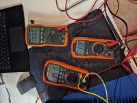
Here are some photos. I got ~350mV with 0V DC offset for both channels. No smoke. No humming. I couldn't test the amp since the Yamaha AS301 doesn't have a pre-out (I thought it did) so now I have to build a phono stage and a preamp with source selection and volume control!! I hate it when that happens 😉.
Thanks to everyone on here for the questions and answers. And especially to the seasoned members for their encouragement and support.
Now that I've built an amp, I am adding a sentence to my profile - "Just build it".
You can spend so much time researching this or that but at some point you just have to stop and build the thing. Remember, you can always build more.
And he started with a very good analogy - basically don't spill the beer!!
Here are some photos. I got ~350mV with 0V DC offset for both channels. No smoke. No humming. I couldn't test the amp since the Yamaha AS301 doesn't have a pre-out (I thought it did) so now I have to build a phono stage and a preamp with source selection and volume control!! I hate it when that happens 😉.
Thanks to everyone on here for the questions and answers. And especially to the seasoned members for their encouragement and support.
Now that I've built an amp, I am adding a sentence to my profile - "Just build it".
You can spend so much time researching this or that but at some point you just have to stop and build the thing. Remember, you can always build more.
Attachments

Congratulations!🙂 Do you have a phone with a headphone jack? If so, you could get a 1/8” to stereo rca adapter cable and use your phone as a source to test the amp. Seems a shame to not be able to hear it after the satisfaction of getting it built and adjusted successfully.
Another short term solution might be a volume pot between tape out of the yamaha and f5 in. That way you get to listen to anything connected to the yamaha at any volume through the f5.
Oh, and still build a phono amp and pre! 😁
Oh, and still build a phono amp and pre! 😁
Congratulations!🙂 Do you have a phone with a headphone jack? If so, you could get a 1/8” to stereo rca adapter cable and use your phone as a source to test the amp. Seems a shame to not be able to hear it after the satisfaction of getting it built and adjusted successfully.
Yeah I think I do lying around somewhere. I'll have to search.
Another short term solution might be a volume pot between tape out of the yamaha and f5 in. That way you get to listen to anything connected to the yamaha at any volume through the f5.
Oh, and still build a phono amp and pre!
Well so long as I get to build those two things...
Thanks for the suggestions
Folks:
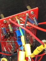
I could use some help. Yesterday, while listening to Be Bop Deluxe's incomparable Shine (off of their Live In The Air Age album, and well worth seeking out), one of my F5 Turbo V3 mono blocks gave up its magic smoke. I turned power to the amp off about 5 seconds later. I haven't begun tearing the amp apart yet but have put it on my bench and have located a region of toasted resistors on the front-end board (see the photo below).
Aside from R26, R6, R28 and R4 (viewed L to R in the photo), everything else in the amp appears intact.
The amp is 6.5 years old and hasn't given me any trouble since it was completed, but I confess I haven't checked the bias in a very long time. The pcbs in my amp are from the Store, version 2.2 (not the current v.3).
My questions:
A copy of the F5 T V3 schematic is attached.
Thank you!
Regards,
Scott
I could use some help. Yesterday, while listening to Be Bop Deluxe's incomparable Shine (off of their Live In The Air Age album, and well worth seeking out), one of my F5 Turbo V3 mono blocks gave up its magic smoke. I turned power to the amp off about 5 seconds later. I haven't begun tearing the amp apart yet but have put it on my bench and have located a region of toasted resistors on the front-end board (see the photo below).
Aside from R26, R6, R28 and R4 (viewed L to R in the photo), everything else in the amp appears intact.
The amp is 6.5 years old and hasn't given me any trouble since it was completed, but I confess I haven't checked the bias in a very long time. The pcbs in my amp are from the Store, version 2.2 (not the current v.3).
My questions:
- What is the likely cause of this failure?
- Is it likely that other components were damaged when the four resistors failed?
- After disconnecting the power supply from the amp boards and verifying the p.s. is working fine, what do you recommend as my next steps?
A copy of the F5 T V3 schematic is attached.
Thank you!
Regards,
Scott
Attachments
Sangram:
It's a PRP PR9372 resistor, which I believe is 1W.
It's probably worth noting that these amps have seen heavy use since they were completed in early 2014.
Regards,
Scott
It's a PRP PR9372 resistor, which I believe is 1W.
It's probably worth noting that these amps have seen heavy use since they were completed in early 2014.
Regards,
Scott
I'd like to first rule out possible output shorts such as from the speaker connections/cables. Also measure the speaker resistance and compare with the other. Interesting that all the blown resistors are on the lower half.
Nash
Nash
nashbap:
I measured each speaker cable and speaker pair, and both were about 6.2R.
Regards,
Scott
I measured each speaker cable and speaker pair, and both were about 6.2R.
Regards,
Scott
Scott,
The last time I encountered this failure mode, I had to replace both JFETs. The SJ74 was okay but the SK170 was dead. That particular amplifier had no cascode and was running 34V rails.
In your case the failure of the cascode resistors is odd. That is a part of the circuit that sees neither high voltages or currents. I would look at the entire input side properly, and replace all the active components at the very least.
I would use the capacitors indicated on the circuit, and carefully check all the gate resistors on the MOSFETs. Lastly the 10 ohm resistors really need to be around 3W for sufficient thermal margin or 2W if you're feeling lucky. 1W is probably fine for low volumes, but I wouldn't use them in amps driven hard. The calculations for this were given sometime in the original F5 thread, the power rating of this resistor was quite a controversy.
Sangram:
Thank you. That may be the best guidance for moving forwards. However, I've been studying that area of the front-end pcb, and it appears to me that R6 suffered a catastrophic failure; it is unquestionably burnt far more severely than the others. Is it possible that the damage to the other three resistors was simply a result of their proximity to R6?
Oh, and some additional information: yes, the JFETs are cascoded, and the rails are about +/- 44.2 VDC (32 VAC secondaries).
Regards,
Scott
Last edited:
Looks like a cascode failure; pull both JFET's and check.
Replace the burnt resistors and test Q8, replace if necessary.
Reset the bias - P1 & P2 to minimum resistance.
Before reinstalling/replacing the JFET's, intstall some 1K(ish) resistors between the drain and source, measure the voltage at the drain's to ensure the cascodes are functional; if ok, install the JFET's & re-bias.
Itsmee, Sangram, et. al.:
Do you suggest I replace R4 (and R3) with a higher wattage resistor? I could get 5W Mills resistors, for example, though that does seem like overkill. Is there something else you'd recommend instead?
Also, should both the 2SA1837/2SJ74 and 2SC4793/2SK170 combos be checked and/or replaced? In other words, is there reason to believe that the problem isn't isolated in the lower half of that circuit?
Regards,
Scott
You need to do a full check of the entire amplifier channel to try to determine what happened. I suggest you remove the front end board and test every part to see if it is still viable. Do the same with the output stage. When this failure occurred, was there a speaker connected to the amp? If so, I would check it for possible damage from DC input, unless you had a protection board installed.
We’re you running the Jfets near their voltage limit?
Knowing which of the active devices is damaged will help with figuring out what happened.
R6 should only have about 4-5 Volts across it, so the fact that it is totally burnt indicates a failure that applied a large voltage across it. Say 40volts, which would be 1.6 watts, enough to cause it to meltdown pretty quick.
On top of checking all the parts you need to check the wiring to make sure you have no bad connections that could have caused the issue. That includes a possible short happening at the output terminals. There is no quick easy way to fix an unknown catastrophic failure like this. Patient and thorough examination of all the components and connections involved is necessary to prevent the same thing from happening again.
Itsmee, Sangram, et. al.:
Do you suggest I replace R4 (and R3) with a higher wattage resistor? I could get 5W Mills resistors, for example, though that does seem like overkill. Is there something else you'd recommend instead?
Also, should both the 2SA1837/2SJ74 and 2SC4793/2SK170 combos be checked and/or replaced? In other words, is there reason to believe that the problem isn't isolated in the lower half of that circuit?
Regards,
Scott
I have used Vishay wire-wound RS series 3W for both R3,R4 and R7 thru R10, although I don't think that R4 caused your problem but rather a result. Check your output stage very carefully. Also check for any swelling or damage to the Mosfet gate resistors for clues. Make sure you replace P2.
nash
Scott, I don't believe R6 was the original culprit - if you are following the schematic closely, there is actually very little current through it except in the case of a catastrophic failure in the actual input circuitry.
Such a failure typically happens in R3/R4, mostly always in R4 because of the extreme amounts of power it has to dissipate at high output levels. Working back from your 44V rails, the resistors will need to dissipate about 1W peak each and while this is a 1W resistor, it is really not enough. It needs to be upsized to at least 2W, 3W will be safer.
Such a failure typically happens in R3/R4, mostly always in R4 because of the extreme amounts of power it has to dissipate at high output levels. Working back from your 44V rails, the resistors will need to dissipate about 1W peak each and while this is a 1W resistor, it is really not enough. It needs to be upsized to at least 2W, 3W will be safer.
Folks:
Thanks for the guidance! Happily, I have extra sets of all of the active components on the front-end board. A short vacation awaits and I'll order a few passive parts while I'm away (my neighbors look trustworthy, but why give them a chance to prove otherwise?). I'll report back in a few weeks.
Regards,
Scott
Hello
Just wondering if it is more advisable to use a centre-tapped Toroidal or a normal one?
I think I'll build mono blocks and I'll probably be using the DiyAudio PSU.
Just wondering if it is more advisable to use a centre-tapped Toroidal or a normal one?
I think I'll build mono blocks and I'll probably be using the DiyAudio PSU.
To build a + and- supply you need either 2 separate windings or a centre tapped winding. I built monoblock v3 with separate supplies, so 4 boxes total. A lot of work and extra expense. Consider one large chassis and better quality parts as an alternative to monoblocks for probably less cost and maybe even better performance for most speaker loads.
I also used Jensen input transformers to get balanced inputs. This eliminates hum related to ground loops between the monoblock chassis, which can be a problem in some systems.
I also used Jensen input transformers to get balanced inputs. This eliminates hum related to ground loops between the monoblock chassis, which can be a problem in some systems.
- Home
- Amplifiers
- Pass Labs
- F5 Turbo Builders Thread