And of course, after changing the trim pot, there is a very low level hum that was not there yesterday.....which can be noticed on 93 dB speakers from 5 ft out.
I probably should have left well enough alone, but I could not manage that different DC offset , when the other channel is not affected in the same way.
The other difference should be irrelevant... the 2.2K bias resistors were mounted on the other side of the board, so that they would easily be out of the way of the heatsinks on the caddock resistors on the front end board.
Let it warm up and see what happens.
Quiet after warm up. Phew.
DC offset right channel 0.1 mV ( no kidding ).
DC offset left channel 72mV.
Will put the scope on it tomorrow. I intend to clip the scope probe ground clip to the case and measure the speaker output with the probe. This will create a loop with two paths from the chassis safety ground to earth. Is this a concern?
Just wondering.....the stable channel had a solder bridge when it was being biased, so just like a shorting plug. Perhaps the best thing to do is zero P1 and P2 on the bad channel and rebias with a shorting plug in place.....then take it from there,?
Whoa!!!!! You need to slow down and think about this before tearing into the amp and potentially causing more problems. As I see it you are getting sudden shifts in output offset of about 70mv on one channel. This seems to happen when you change input cables, add shorting plugs etc. I think you should carefully check all components and solder joints from the RCA plug to the input fets. And I mean everything, including wires and cable if you are using cable to the input of the FE board. And also any chassis ground connections. Make sure you have the proper value input resistor in place and that you can measure it’s resistance from the RCA plug (47.5K). Same goes for the 1k series input resistor to the input fets. Measure from the fets to the input rca. It should read 1k. It seems most likely to me that you have something not quite right in the input circuit. A change anywhere in the circuit can cause a bias change for one polarity relative to the other which shows up as offset. It is difficult to pin it down. A very careful visual check leaving nothing to chance will often get to the bottom of an intermittent problem like this. I have seen it many times over the years when working on lab instrumentation.
Good luck. - Tip- If you are getting meter readings that don’t make sense ALWAYS check your meter leads and probes for good continuity. Verify the meter by checking it on a known source of voltage before trying to make sense out of the readings.
Good luck. - Tip- If you are getting meter readings that don’t make sense ALWAYS check your meter leads and probes for good continuity. Verify the meter by checking it on a known source of voltage before trying to make sense out of the readings.
OK, I go slow.
I've made sure the FE boards are totally stock. No funny stuff that I probably don't fully understand how to implement.
I have put in shorting plugs and am biasing the left channel. Will let this sit for a couple hours watching the DC offset and the voltage across the test points on all boards.
I have not started to bias the right, as all 5 meters are in play on the left channel.... going slow...
I suspect I should check the bias with the shorting plug out as well....
Bfpca
I have to say the matching you did on these is fantastic!
I've blown up so many, I can barely get a good set together... but even with what I have left, I am reading 277, 275, 273.8 and 290 mV, at a 0.1 mV DC offset on the left channel.
These parts are excellent. I highly recommend if people want to get well matched outputs, they should ask for what you have in stock.
shorting plug out:
LEFT CHANNEL IS STABLE. DC offset is the same 0 +/0 0.5 mV.
EXCELLENT.
On to the right channel.
LEFT CHANNEL IS STABLE. DC offset is the same 0 +/0 0.5 mV.
EXCELLENT.
On to the right channel.
YESSS!!! both channels are stable, shorting plugs vs no shorting plugs.
WOOOT!!
Thank you for telling me where to look Bfpca! I needed to know.
It sounds awesome as it should! HOLY SMOKE IS IT BETTER!!!
WOOOT!!
Thank you for telling me where to look Bfpca! I needed to know.
It sounds awesome as it should! HOLY SMOKE IS IT BETTER!!!
Last edited:
Well I added the HBRs -- two 1 ohm 5 watt source resistors in series. It all came up nicely, pretty much straight to 0 mv offset. I measured the right channel noise and THD. Looked fine.
Turned off the amp.
Moved the analyzer to measure the left channel. Turned it on. After the relays clicked in, heard a buzzing noise. Then the speaker protection went on and the fuse blew.
I had reversed the analyzer ground and amp hot.
Change the fuse.
It comes up right away to -60 mV.
Looks like I might have fried an output or two....but no smell, no smoke.....
I was done!!!!
Last edited:
All individual outputs show that the "right" amount of current is going through each source resistor. DC offset looks back to normal.
What just happened????
What just happened????
Last edited:
My testing procedure:
Start one side at a time with dim bulb
No problems check biasing
No problems check DC offset
No problems, plug in speakers and listen
No problem check temps
No problem put the lid on and listen, check temps again
Temps fine smile an listen to another awesome pass amp. I don't go looking for problems unless I hear something I don't like. I don't put a lot of stock in what some electronic device tells me sounds good or bad. In fact, I tend to like Pass designs that have more distortion rather than less... go figure.
To clean and I think you have a guy in a suit, I'm more of a ripped jeans and long hair type. 🙂
Thanks thompsontechs. I was listening last night, prior to adding the HBRs. It sounded great, but had that buzzing. Since then the right channel was measured and that noise level is back to normal.
I hope that at least my adventures here are amusing and and not too annoying.
Everything here looks OK again., I am going to check the bias again on that channel, as I noticed that the thermistor somehow got lifted away from the output device on the p channel.
My next build will focus on the quality of the layout and it's connections.
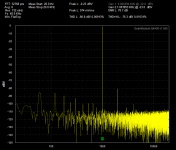
Just to check the analyzer, and for fun, here are the distortion/noise figures for the channel that just popped the fuse.
I hope that at least my adventures here are amusing and and not too annoying.
Everything here looks OK again., I am going to check the bias again on that channel, as I noticed that the thermistor somehow got lifted away from the output device on the p channel.
My next build will focus on the quality of the layout and it's connections.
Just to check the analyzer, and for fun, here are the distortion/noise figures for the channel that just popped the fuse.
Attachments
It could have been this.All individual outputs show that the "right" amount of current is going through each source resistor. DC offset looks back to normal.
What just happened????
Things likely got pretty hot before the fuse blew. So when you tried it the first time there may still have been some hot parts, or at least some that were warmer than normal at startup, that shifted the operating point enough to move the offset by 60mv. After it was all cooled down to room temp the operating conditions returned to normal.
The distortion number is certainly good. You do have some power line related noise starting with the 60hz peak in the analyzer display and going up through the harmonics of 60hz. I believe you have 2 transformers in the chassis which makes it easy for this to happen. Not enough space to keep everything well separated.
You are certainly not the first to connect test equipment up backwards. Scopes and analyzers with the negative side grounded are the cause of a lot of damage.
I once bought a set of class D monoblocks with tube buffers that were demonstrators. One had hum and when I took the cover off to change the input tube I could smell that something had burnt. It turns out some journalist who was testing the amps connected an oscilloscope ground lead to the - speaker terminal. The amp had a bridged output so he directly grounded that terminal. The 500+watt amp scorched the wiring and melted some stuff. The amp still worked but had more hum than it should. Nobody would confess to doing the damage. I sent the amps back and got my money returned.
Many oscilloscope probes have meant their maker when the ground lead is connected to the hot side of the line by mistake.
Last edited:
After seeing good values for voltage drop across all source resistor pairs, I suspected something like overheating. It's been playing for over an hour now, and all four heatsinks seem the same temp... and the 24 degree heat rise is as expected.
If one or more output devices were popped, the heatsink they are mounted on would be cooler.
The good thing is that I know the 5A fast blow fuse is a decent value. There was a HF buzzing before it let go. It thought my laptop harddrive was starting to make whirring sounds. I suspect now the fuse was making that noise.
The amp sounds really great. The noise is not at all audible on the 93 dB efficient speakers.
There's nothing like hearing music appear from nothing the first time.
I have a question:
There are 5 sets of secondaries on the main transformer. I guess this was a power supply intended for an AVR. They are wired for 30-0-30.
4 are in use, and all of those center taps are hooked to their power supply 0 volt line.
( Dual mono, two power supplies, two zero volt lines, 2 secondaries to one power supply 2 to the other.)
The unused secondaries are curled up, covered in heat shrink and taped up.
Should the CT of the unused secondary be attached to one of the zero volt lines?
Hello all!
I would like to know how to operate class A. Please explain.
Now I have set the bias at .28 V across 1 ohms. I have 2 pair of output devices in parallel and a 42 V power supply.
Thank you much!
I would like to know how to operate class A. Please explain.
Now I have set the bias at .28 V across 1 ohms. I have 2 pair of output devices in parallel and a 42 V power supply.
Thank you much!
The other night, I listened for 6 hours. The sound got better as the heat went up. At the end of the night the heatsink temps were 47 deg C and DC offsets were 1.2 mV and -0.8mV.
Since I no longer want to risk blowing it up again, am calling this build complete.
THANKS TO EVERYONE.
No way could I do this without you.
Cheers!!!!
Since I no longer want to risk blowing it up again, am calling this build complete.
THANKS TO EVERYONE.
No way could I do this without you.
Cheers!!!!

- Home
- Amplifiers
- Pass Labs
- F5 Turbo Builders Thread