I have found that the in-rush current to a discharged capacitor bank tapers off quickly, after a few seconds, I set the soft start circuit to 10 seconds which is long enough to keep from tripping the circuit breaker and not so long that the Thermistor gets too hot.
One minute is a bit of over kill but won't hurt.
One minute is a bit of over kill but won't hurt.
As said above, 10 seconds should do. Another consideration is that if you leave it in circuit for 1 minute it will have the continuous current draw of the amplifier running through it for that time. That will cause it to be hotter than it would be after just 10 seconds. If you are worried about the time for it to cool between power cycles it makes more sense to not leave it on any longer than necessary and thus get a shorter cooling time.
A simulation in LTspice showed that 1 minute was necessary to fill the capacitor bank enough so that the current through the relays stays below 15 amps when switching over.
The capacitor bank was powered with no load. The positive rail voltage for each channel is 40.3 Volts. The negative looked like the same magnitude.
That should drop a little with load, so it may be possible to get 100 watts at 4 ohms.
But for nasty speakers, it is probably better to bias to an even lower value. Maybe 3 ohms?
I have an amp with +/- 48volts rails and 3/4 of a farad total capacitor banks and I only need 3 seconds to get past the massive in-rush. I used 10 ohm thermistors for 120v amps and 20 ohms for 240v to keep the in-rush limited to 12 amps until the bypass relay pulls in after 10 seconds.
Your bias level will depend on how much cooling you have to keep the output devices at an acceptable temp.
Your bias level will depend on how much cooling you have to keep the output devices at an acceptable temp.
IIRC, the simulation showed that a difference of just 5 volts between rail voltage and switchover voltage was enough to cause a spike of over 20 amps at the relay contact. The rail voltage I used at the time was 46-48 volts.
In real life, the time it takes with 40 volt rails to get to 90% of rail voltage for my capacitor bank is about 15 seconds. That cap bank is not huge -- I use Teabag's white board, one per channel. That is without the load of the bias current of the output section.
The installed relays have a 20 amp max current capacity rating. A spike over 20 amps may damage them. This is from memory--the relay may have max 15 amps....whatever, 15 amps is never exceeded ).
New Keratherms and extra PCBs ordered.
I wish we could just get output PCBs to lower the cost.
I wish we could just get output PCBs to lower the cost.
IIRC, the simulation showed that a difference of just 5 volts between rail voltage and switchover voltage was enough to cause a spike of over 20 amps at the relay contact. The rail voltage I used at the time was 46-48 volts.
In real life, the time it takes with 40 volt rails to get to 90% of rail voltage for my capacitor bank is about 15 seconds. That cap bank is not huge -- I use Teabag's white board, one per channel. That is without the load of the bias current of the output section.
The installed relays have a 20 amp max current capacity rating. A spike over 20 amps may damage them. This is from memory--the relay may have max 15 amps....whatever, 15 amps is never exceeded ).
How detailed is your Spice sim? If that relay is in the primary of the transformer there are a lot of current limiting factors that will reduce peak current.
I have not modeled the transformer with any sort of accuracy. IIRC, I think I have added some resistance to the windings. That is all.
The relay is between the secondary and the capacitor bank.
There are actually two relays in series. The first relay connects the secondary to the thermistor. This has a delay timer that ensures the thermistor has cooled and will function as a thermistor again in the event of short cycling the power.
The second connects the thermistor to the capacitor bank via NC contact, then bypasses the thermistor after the capacitor bank has filled enough.
The issue I am trying to avoid is the current surge through the contacts of the bypass relay. Not sure if that has much to do with the transformer modeling.
Ah! You have the thermistor in the secondary. Current will be higher in the secondary. How large is your transformer? I have 800va in my F5V3 monoblocks and use about a 10-15 second delay before bypassing the thermistor. I’m running about 45volt supplies and IIRC it gets up to over 40volts before switching out. The filter is CLC- 90kuf-10mh-150kuf. The thermistor does not seem to get very hot and I don’t see any arcing in the relay at switchover. The relays are in the primary.
The filter is CLC- 90kuf-10mh-150kuf.
I would like to see the inductors you are using that are 10 mH and current capable for a F5V3.
They must be HUGE !
How many amps are they rated?
And where did you get them?
Rush
I would like to see the inductors you are using that are 10 mH and current capable for a F5V3.
They must be HUGE !
How many amps are they rated?
And where did you get them?
Rush
My mistake, They are actually 30mh. I documented the build with some photos here F5 Turbo Builders Thread
They are rated at either 10 or 12 amps, I can’t remember exactly. This type of choke will buzz if you try to use it in an LC filter but is silent in a CLC. For reference the toroid in the photos in post 4673 is 800va. I got them from a surplus metal dealer. I used to have a friend who worked there and would pull interesting junk out for me. Alas he is no longer working there so that source has dried up.
Ah! You have the thermistor in the secondary. Current will be higher in the secondary. How large is your transformer? I have 800va in my F5V3 monoblocks and use about a 10-15 second delay before bypassing the thermistor. I’m running about 45volt supplies and IIRC it gets up to over 40volts before switching out. The filter is CLC- 90kuf-10mh-150kuf. The thermistor does not seem to get very hot and I don’t see any arcing in the relay at switchover. The relays are in the primary.
I have a transformer with 5 secondaries,each 60 V No Load, total 2.4 KVa, assuming primaries wired for 120V. It originally provided balanced system power, but I did not like it much and the implementation was stupid. ( First ever attempt at making something from scratch -- it looked like an octopus. Looking back, I should have built a proper enclosure and used the DIYaudio soft start circuit.)
The transformer is wired for 240 volt operation, so when applying 120 V the output drops to 1.2 KVA.
Four secondaries (2 per channel) are used to make it sort of a dual mono amp in a single enclosure. The 5th secondary is unused.
That makes it 960 VA total, or 480 VA/channel.
The 5th secondary should be used to power the speaker protection and slow charge capacitor bank circuits, by using a voltage divider to get it down to providing 12 Volts DC. But it's got another small transformer in there doing that duty right now, and I am a little bit too lazy.
Has anyone built a F5 T V2 using single FQA28N15 and FQA36P15 per channel? Or can anyone here find reason not too? TIA oh wise ones...
Bulb tester removed, P1/P2 zeroed.
Power applied, rail voltage(34v)still present at TP1/TP2.
Trimming commenced. At about eight turns heat becoming apparent at mosfets (P channel warmer than N channel), rail voltage reducing with trimming.
At about fourteen turns of P1/P2, outboard N channel mosfet failed (little flash and smoke!!).
Investigation showed, source leg of outboard N channel mosfet to have sustained significant damage.
Woops
Failed N channel MosFet (also NCT)replaced.
Before I proceed further I need to understand why there is rail voltage (34v) present at TP1/TP2. here are a couple of photos of the build, can anyone see a problem.
Attachments
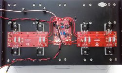
In this image from espirit, the power and control wiring is such that the two output boards are paralleled.
Is this approach better than running the two boards in series? ie where power comes from one end and control/output from the other?
Is the *shortest* wiring best?
Is this approach better than running the two boards in series? ie where power comes from one end and control/output from the other?
Is the *shortest* wiring best?
Attachments

That's not my work in the photo.
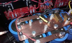
In my amp, I have the cap bank on the front of the amp, and the input boards on the back. The output boards are wired in series. I can show a photo of the arrangement later, but it is still in pieces.
In my amp, I have the cap bank on the front of the amp, and the input boards on the back. The output boards are wired in series. I can show a photo of the arrangement later, but it is still in pieces.
On the soft start circuit I like to limit on the Primary side of the transformer for several reasons. 1. The voltage may be higher but the currents are generally lower, I limit them to no more than 12 amps, two 5 ohm thermistors in series for 120v, and two 10 ohms thermistors in series for 240v, each thermistor good for 17 amps. 2. You can use a triac, which doesn't mind the higher voltage, instead of your first relay, use a zero-crossing detector to trigger the triac so it starts on an AC null. Then use a voltage comparator to trigger a MOSFET to pull in the relay that bypasses the thermistors.
I think that is a really good idea, because it would eliminate a lot of parts/relays in my amp.... specifically, it would cut the number of relays on the secondary side in half because I have two independent capacitor banks.
If I were to implement such a circuit, I would use a timer to switch the thermistors out of circuit, as it is within my comfort zone.
If I were to implement such a circuit, I would use a timer to switch the thermistors out of circuit, as it is within my comfort zone.
- Home
- Amplifiers
- Pass Labs
- F5 Turbo Builders Thread