Yes, the rail voltage needs to be locked together or the bias will run away.
Rush
Yup:
https://www.diyaudio.com/forums/pas...ted-ps-power-amp-input-stage.html#post3647204
Hi BigE,
Are you saying you want to wire a 4 ohm power resistor in series with your speakers
so the amp sees an 8 ohm load?
Does your transformer have two primaries? If so, have you considered wiring them
in series to lower the output voltage to half?
Dennis
Are you saying you want to wire a 4 ohm power resistor in series with your speakers
so the amp sees an 8 ohm load?
Does your transformer have two primaries? If so, have you considered wiring them
in series to lower the output voltage to half?
Dennis
Hi BigE,
Are you saying you want to wire a 4 ohm power resistor in series with your speakers
so the amp sees an 8 ohm load?
Does your transformer have two primaries? If so, have you considered wiring them
in series to lower the output voltage to half?
Dennis
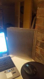
No. I'd use the 4 ohm resistor to set the bias to a level that my heatsinks can manage. Here is a pic of one.... I will be using 4. Each will have a DIYaudio output section on it -- that's a pair of positive on one sink and a pair of negative on the other.
Attachments
Here is the data sheet for the transformer.
I've wired it so that it produces much lower output voltage; about 30 volts AC, when rectified is 42. But my wall plugs are overvoltage a bit, which gets me to 46 or 48.
I've not started the transformer in a while. Going to do that today.
I've wired it so that it produces much lower output voltage; about 30 volts AC, when rectified is 42. But my wall plugs are overvoltage a bit, which gets me to 46 or 48.
I've not started the transformer in a while. Going to do that today.
Attachments
That is the heatsinksUSA's 10.080" profiles 10"long?
As long as you get the heat spread over the sinks backplate, you should be fine. I use those sinks in 6" lenght. and they can handle 100W of heat dissipation each without problems.
As long as you get the heat spread over the sinks backplate, you should be fine. I use those sinks in 6" lenght. and they can handle 100W of heat dissipation each without problems.
Excellent! Thanks for the link.
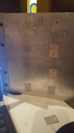
Mount the outputs 1/3 up from the bottom. And distance between outputs should be around 10X the baseplate thicknes. on this sinks, that is 9mm. So 90mm between outputs. And no more then 10x baseplate thicknes (so 90mm) from edge to first output. And from edge to last output. add it all togheter and you get 270mm. Just about perfect. But i would limit the heat dissipation pr outputdevice to 30W to get some lifetime out of them.
Last edited:
AudioSan,
Thank you for the mounting specs! I will have to redrill for sure. At most 48 holes -- 8 for one board, 2 for the mosfets and 2 for the diodes. So 12x4 boards.
I think I can manage that!
Thank you for the mounting specs! I will have to redrill for sure. At most 48 holes -- 8 for one board, 2 for the mosfets and 2 for the diodes. So 12x4 boards.
I think I can manage that!
Just keep in mind the Maximum dissipation pr device. With your rail voltage and speakerload, i would use 4 output pairs.
You may then have to Mount the outputs 1/2 up from the bottum of the sinks. with one PC Board over the outputs and one PC Board below the outputs. with the diodes over and under. Then you get a raw of 4 outputs pr sink, in the midle. That works fine. No worries. The diodes don't need the cooling per say. They just need the temeperature te be even thruout the diodes.
You may then have to Mount the outputs 1/2 up from the bottum of the sinks. with one PC Board over the outputs and one PC Board below the outputs. with the diodes over and under. Then you get a raw of 4 outputs pr sink, in the midle. That works fine. No worries. The diodes don't need the cooling per say. They just need the temeperature te be even thruout the diodes.
Last edited:
Well that means less work.
However, all outputs are currently not quite at the center. They are currently drilled 1/3rd up from the bottom, 1/3 down from the top. That's about 70-75 mm between them at the center.
A P-channel board and an N-channel board on the same sink makes wiring simpler.
However, all outputs are currently not quite at the center. They are currently drilled 1/3rd up from the bottom, 1/3 down from the top. That's about 70-75 mm between them at the center.
A P-channel board and an N-channel board on the same sink makes wiring simpler.
Whilst initially trimming P1 & P2, I have discovered that I have rail voltage (34v) at TP1 TP2, on both channels. This voltage reduces and the test lamp begins to light up with further trimming.
Please help !
Please help !
You chould NEVER have a testbulb when you turn up the bias. It's only ment to discover faults in the build. It will light up when there is a current draw. And guess what. when you turn up the bias, you get a current draw. If you adjust the bias with the bulbtester in Place. You will have a lot higher bias when you remove it. And the amp will burn up.
Well that means less work.
However, all outputs are currently not quite at the center. They are currently drilled 1/3rd up from the bottom, 1/3 down from the top. That's about 70-75 mm between them at the center.
A P-channel board and an N-channel board on the same sink makes wiring simpler.
I don’t think it will make that much difference as far as location goes. Top or bottom 1/3 should both work. I don’t think there is any mechanism for heat convection within a solid. It may make some positive difference with the air convection at the fins with the bottom of the sink heating up first using the lower mounting position. However the heat within the sink itself will not spread faster up the sink than down.
Well that means less work.
However, all outputs are currently not quite at the center. They are currently drilled 1/3rd up from the bottom, 1/3 down from the top. That's about 70-75 mm between them at the center.
A P-channel board and an N-channel board on the same sink makes wiring simpler.
Perfect I always start 1/3 from the bottom.
Well that means less work.
However, all outputs are currently not quite at the center. They are currently drilled 1/3rd up from the bottom, 1/3 down from the top. That's about 70-75 mm between them at the center.
A P-channel board and an N-channel board on the same sink makes wiring simpler.
1/3 from bottum or 1/2 up. just juse New fresh drilled holes.
and watch the distance te the edge of the sinks. THATS the realyy important thing.
Bulb tester removed, P1/P2 zeroed.
Power applied, rail voltage(34v)still present at TP1/TP2.
Trimming commenced. At about eight turns heat becoming apparent at mosfets (P channel warmer than N channel), rail voltage reducing with trimming.
At about fourteen turns of P1/P2, outboard N channel mosfet failed (little flash and smoke!!).
Investigation showed, source leg of outboard N channel mosfet to have sustained significant damage.
Woops
Thanks for the advice!
I need to get a couple keratherms, and will be on the way.
Last night I powered up the transformer and ancillary circuits, those being speaker protection and capacitor bank startup circuitry.
In the startup circuitry, the power to the capacitor bank is delayed for 1 minute to allow the thermistor to cool from potentially previous short power cycling.
The thermistor is kept in circuit for one minute while the capacitor bank is charged, then switched out. This avoids the thermistor being in circuit when the amp is running.
It also allows the thermistor to cool so that it can once again be effective on power start.
Tonight, the capacitor bank is connected, and rail voltage checked. It should be quite a bit lower.
- Home
- Amplifiers
- Pass Labs
- F5 Turbo Builders Thread