A 5A fuse can pass >1kA in the first few microseconds until it becomes hot enough to rupture and the arc to extinguish.
Have you considered testing your lower rated Disconnecting Network?
I have never seen any other Forum Member publishing a test report for a mains to chassis fault.
Are you going to test your Disconnecting Network to >1kA?
Have you considered testing your lower rated Disconnecting Network?
I have never seen any other Forum Member publishing a test report for a mains to chassis fault.
Are you going to test your Disconnecting Network to >1kA?
Last edited:
The diode bridge should have peak repetitive current rating of more than the largest circuit breaker in the entire household circuit. That way it will not be the first to melt.
Continuous rating is less important in this application. The 100mS rating is a good guide as most breaker will trip at that point.
Continuous rating is less important in this application. The 100mS rating is a good guide as most breaker will trip at that point.
The MCBs in my distribution board are rated at 10kA. I have seen others rated at 5kA, 6kA and 10kA.The diode bridge should have peak repetitive current rating of more than the largest circuit breaker in the entire household circuit. That way it will not be the first to melt.
Continuous rating is less important in this application. The 100mS rating is a good guide as most breaker will trip at that point.
Sorry, I meant to post here. sorry for the repost.
So, got a bit impatient as the bridge hasn't arrived so I basically have the CL-60 going from circuit ground to IEC earth. When I started things up, it smoked and burned red (it took a few seconds). I turned it on again (heh) and it smoked immediately. That was interesting. The CL-60 seems to measure as a short now. Earth and ground seem to be shorted now (as you'd expect). No fuses went, I have a glass 2.5A on the outside and two resettable 2.5A fuses on up the circuit.
I disconnected the power supply load and, well, it smokes without any load connected on a variac as well (not yet up to full mains voltage). seems like no current should be flowing from ground to earth? no transformer connected, no smoke. so that at least is good. odd. what should i check? I don't see any obvious shorts, etc.
Perhaps the F4 style dual bridge with a thermistor to ground is "different" than the F5T arrangement, where the F5T "needs" the bridge and not a simple thermistor to ground?
Last edited:
Removed the dead TH and the amp came up just fine. So, you need both in this amp, but just the TH in the F4 for some reason other than safety.
I've used all sorts of isolating configurations, and if you see appreciable current through the network (of any kind) it indicates a serious miswiring fault. All the networks do pretty much the same thing and in normal conditions there will be very little voltage across/very little current through it. This applies to resistors and thermistors with and without diodes.
I would examine the board wiring carefully, and check the potential of the chassis and circuit grounds relative to mains earth. Something isn't right if you're smoking the thermistor. It sounds like your PSU ground is coupled to one of the mains power terminals - that's the only thing that would cause a current to flow through that component. I advise you to proceed very gingerly.
I would examine the board wiring carefully, and check the potential of the chassis and circuit grounds relative to mains earth. Something isn't right if you're smoking the thermistor. It sounds like your PSU ground is coupled to one of the mains power terminals - that's the only thing that would cause a current to flow through that component. I advise you to proceed very gingerly.
This should be measurable with things off though, and I don't find this to be the case. The output grounds are connected to the PSU and isolated from the case. The earth terminal goes straight to the case through the PSU PCB. I will keep looking, thank you for the advice.
The mains earth does not go through any other component.
The Protective Earth wire in the mains cable goes directly to the chassis.
You have a similar question in another Thread.
You need to go and look.
The Protective Earth wire in the mains cable goes directly to the chassis.
You have a similar question in another Thread.
You need to go and look.
Please post a photo or two of your wiring, if a CL-60 burned up as a ground breaker, you absolutely have an error somewhere.
The real difference here is the F5T PSU has an awful lot more stored energy than a 'standard' FirstWatt PSU. So if there is a fault, that energy needs to make it to ground before the escape mechanism fails. The big diode bridge + CL-60 ground breaker in the F5T PSU keeps GND elevated off earth by about 1.4v plus some of the cold resistance of the CL-60. But if there's a fault, the current need only flow through the easy path of the diodes to ground.
That said, this arraignment does the exact same thing as the single CL-60, it elevates signal ground by some ohms to keep ground loops from forming though the safety earth connection, but also gives a path to ground in case of a fault.
Perhaps the F4 style dual bridge with a thermistor to ground is "different" than the F5T arrangement, where the F5T "needs" the bridge and not a simple thermistor to ground?
The real difference here is the F5T PSU has an awful lot more stored energy than a 'standard' FirstWatt PSU. So if there is a fault, that energy needs to make it to ground before the escape mechanism fails. The big diode bridge + CL-60 ground breaker in the F5T PSU keeps GND elevated off earth by about 1.4v plus some of the cold resistance of the CL-60. But if there's a fault, the current need only flow through the easy path of the diodes to ground.
That said, this arraignment does the exact same thing as the single CL-60, it elevates signal ground by some ohms to keep ground loops from forming though the safety earth connection, but also gives a path to ground in case of a fault.
The odd thing is XLR pin 1 and PSU ground (therefore signal ground also) show zero ohms to the chassis. PE goes directly to the chassis as well. So, how there could be current running through a TH from PE to PSU GND is baffling. I am using a remote momentary switch to trigger a relay to turn on the amplifier. To power this, small transformer is connected as "always on" to mains. The ground of this little circuit floats as best as I can tell.
I can post some pictures, I already see a few changes that I should make - moving this small transformer after the main fuse, for example. I post things as-is though, so perhaps we can diagnose why the TH went smoky the bear.
I can post some pictures, I already see a few changes that I should make - moving this small transformer after the main fuse, for example. I post things as-is though, so perhaps we can diagnose why the TH went smoky the bear.
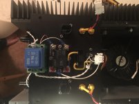
Ok, here's a basic shot. The white wires on the right go to a NC thermal breaker (which is attached to each heatsink uninsulated). The covered wires with the black nylon go back to the momentary switch used to trigger the relay. As noted above, the auxiliary transformer should be after the mains fuse. I think the basic circuit here is obvious enough:

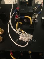
In the second shot, you see the connector that supplies triggered AC to the power supply. The far right wire comes form switched "Live" and the "Neutral" and "Earth" come directly off the IEC plug.

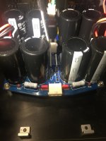
Here's the plug on the circuit board, it's pretty clear what goes where. The "Live" wire goes to a thermal switch, "Neutral" goes through a jumper wire over to the other side of the board where the transformer sits and the "Earth" goes via a trace to the screw that mounts the board. I think this is similar to what the First Watt amplifiers implement. You can also see where the smoking TH was removed and the non-populated bridge. Before you ask, the other side of this standoff has a screw is connected to bare metal via a counterbore. All of the various panels are earthed together via similar arrangements, including the heatsinks themselves.

edit: my images are getting squashed, but click on the thumbnails below for non-squashed versions.
In the second shot, you see the connector that supplies triggered AC to the power supply. The far right wire comes form switched "Live" and the "Neutral" and "Earth" come directly off the IEC plug.
Here's the plug on the circuit board, it's pretty clear what goes where. The "Live" wire goes to a thermal switch, "Neutral" goes through a jumper wire over to the other side of the board where the transformer sits and the "Earth" goes via a trace to the screw that mounts the board. I think this is similar to what the First Watt amplifiers implement. You can also see where the smoking TH was removed and the non-populated bridge. Before you ask, the other side of this standoff has a screw is connected to bare metal via a counterbore. All of the various panels are earthed together via similar arrangements, including the heatsinks themselves.
edit: my images are getting squashed, but click on the thumbnails below for non-squashed versions.
Attachments
With at least 5 white wires most of which are not in pairs your pics are pretty unclear where any current is going !
With at least 5 white wires most of which are not in pairs your pics are pretty unclear where any current is going !
Color coding would be nice. Just look at where they go? I wouldn't say "most" aren't in pairs...
Last edited:
You may want to check if the body of the thermal switch is isolated from the live wire. I had a bad experience with a thermal switch where the metal body is actually connected to one of the wires.
You may want to check if the body of the thermal switch is isolated from the live wire. I had a bad experience with a thermal switch where the metal body is actually connected to one of the wires.
I like that theory. Here's the datasheet, I can verify tonite:
http://airpax.sensata.com/pdfs/6700.pdf
Looking at this, (for 20min, this is not an obvious problem at all...) I need to ask a few question -
The Thermal - in your photos, it's the doohickey on the long white leads. What's the TO-220 thing you linked to? If thats in-circuit and connected to heatsink, with no insulator, that might be the issue.
Looking at the layout an schematic of your PCB, http://www.diyaudio.com/forums/swap-meet/297805-fs-yafwpsu-yet-another-firstwatt-psu.html
Are the mounting leg holes connected to anything? Hopefully they float.
😱😱😱
That scares the living bejeezus out of me. Is your chassis floating but hot? According to the schematic there's no reason why having it connected or disconnected should make one iota of difference in regards to power-up.
Lastly, and do this immediately - Connect safety earth from the IEC directly to the chassis with a stud and star washer and then connect your PSU PCB earth to that, NOT the IEC plug.
The Thermal - in your photos, it's the doohickey on the long white leads. What's the TO-220 thing you linked to? If thats in-circuit and connected to heatsink, with no insulator, that might be the issue.
Looking at the layout an schematic of your PCB, http://www.diyaudio.com/forums/swap-meet/297805-fs-yafwpsu-yet-another-firstwatt-psu.html
Are the mounting leg holes connected to anything? Hopefully they float.
Removed the dead TH and the amp came up just fine.
😱😱😱
That scares the living bejeezus out of me. Is your chassis floating but hot? According to the schematic there's no reason why having it connected or disconnected should make one iota of difference in regards to power-up.
Lastly, and do this immediately - Connect safety earth from the IEC directly to the chassis with a stud and star washer and then connect your PSU PCB earth to that, NOT the IEC plug.
Looking at this, (for 20min, this is not an obvious problem at all...) I need to ask a few question -
The Thermal - in your photos, it's the doohickey on the long white leads. What's the TO-220 thing you linked to? If thats in-circuit and connected to heatsink, with no insulator, that might be the issue.
Exactly. I'll check this tonite.
Looking at the layout an schematic of your PCB,
Are the mounting leg holes connected to anything? Hopefully they float.
Mounting leg holes of what exactly?
😱😱😱
That scares the living bejeezus out of me. Is your chassis floating but hot?
I'm not sure, it doesn't shock me 🙂 I suppose I can measure voltage from myself to the chassis...
Lastly, and do this immediately - Connect safety earth from the IEC directly to the chassis with a stud and star washer and then connect your PSU PCB earth to that, NOT the IEC plug.
I'm looking at a number of First Watt amplifiers and trying to understand how this is done. I do see "E" on the screw mounting terminals of the PSU and a green/yellow wire going off to perhaps a mounting foot. So, that jives with what you're saying. Anyone have a better picture on how this is configured?
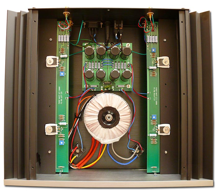
The green/yellow of earth goes off somewhere and then there is a solid green that goes to the IEC mounting hardware. Then a wire that comes back to the PSU PCB?
Last edited:
easy peasy
IEC safety pin -fat wire goes to chassis - eyelet to one screw with nut and proper zingie washer
then connect audio GND -fat wire - eyelet to that screw on chassis
do not underestimate fact that every metal chassis must be connected to safety gnd;
everything else is secondary to that , importance wise
Ok, hardwired Earth to chassis. The thermal breakers don't show continuity between either pin and the case, isolated then anyways. I get 4.8 VAC between myself and the chassis, nothing smoking (no TH). What to check next?
Ok, an interesting finding. The power switch driver is documented here:
http://www.amb.org/audio/epsilon24/
Now, the back of the regulator and the back of the MOSFET read 12.2 VAC to earth. So do the terminals connecting to the momentary switch and it's embedded LED. So, this circuit is floating above earth for sure.
http://www.amb.org/audio/epsilon24/
Now, the back of the regulator and the back of the MOSFET read 12.2 VAC to earth. So do the terminals connecting to the momentary switch and it's embedded LED. So, this circuit is floating above earth for sure.
- Home
- Amplifiers
- Pass Labs
- F5 Turbo Builders Thread